Flight control system and method of using piezoelectric modal sensors to mitigate flexible body dynamics

a flexible body and control system technology, applied in the field of flight control systems, can solve the problems of system self-exciting vibration, system instability, system failure, etc., and achieve the effect of reducing the risk of system failure, and simple and inexpensive mechanisms

Active Publication Date: 2010-01-12
RAYTHEON CO
View PDF6 Cites 6 Cited by
  • Summary
  • Abstract
  • Description
  • Claims
  • Application Information

AI Technical Summary

Benefits of technology

[0014]The present invention provides a simple and inexpensive mechanism to sense and mitigate the effects of flexible body dynamics on the flight control system for a flight vehicle.
[0015]This is accomplished with one or more modal sensors that are each configured to measure the rate and possibly acceleration for a flexible body mode of the flight vehicle. The modal sensor's rate and suitably acceleration are subtracted from the rate and acceleration measured by the IMU such that the values provided to the flight controller more closely represent only the rate and acceleration of the flight vehicle's rigid airframe component. The sensor must be capable of sensing the mode over variations in the modal frequency without inducing additional phase loss in the control loop in order to maintain suitable gain and phase margins. In an embodiment, each sensor is configured to sense one and only one mode, e.g. a 1st lateral bending mode. Multiple modes can be sensed using multiple sensors each configured for a specific mode.

Problems solved by technology

These flexible body dynamics introduce an unwanted signal to the control loop response.
The flight control system must be designed to compensate for these flexible body dynamics or the system could have self-exciting vibrations.
In the case where these vibrations are not bounded, catastrophic structural damage and mission failure will occur.
In the case where the vibrations remain finite, the additional frequency content in the actuator commands can lead to actuator failure due to overheating and mission failure.
If the flight controller has sufficient bandwidth and minimal latency it may be possible to actuate the control surface to directly compensate the 1st lateral bending mode but this requires a lot of power and places considerable stress on the actuators and flight controller.
If the phase-margin is too small then small unmodeled time delays in the real system could result in an unstable control loop.
If the gain-margin is too small then small variations in the real system gain could result in an unstable control loop.
In missiles and other flight vehicles, the 1st lateral bending mode is typically large enough that the gain of the control loop at the mode frequency, which would otherwise be −20 to −30 dB, is greater than 0 dB, and thus has the potential to become self-excited and destabilize the control loop.
This approach can work but is expensive because the actuator mechanisms must be carefully designed and manufactured to dampen and not excite the 1st lateral bending modes and the location of the IMU is critical.
Phase loss is a non-dimensional measure of latency which negatively affects the flight control system's ability to track the input commands.
Too much latency can result in an unstable closed loop system.
However, this is impractical due to the inherent uncertainty of the flexible dynamics that results from the variability that occurs during the missile manufacture.
Often, the digital notch filters are designed to shift with the frequency, and vary with flight condition, but manufacturing uncertainty necessitates wider and deeper notch filters.
In many systems this would be considered either marginally acceptable or unacceptable because both the gain margin and phase margin are lower than would typically be allowed (4 dB and 20° being typical gain and phase margin design goals).
This approach has been used in very large expensive rockets whose lower frequency flexible body mode frequencies are within the bandwidth of the flight control system required to stabilize the rocket.
This approach is not practical for small low cost lightweight missiles whose lower frequency flexible body mode frequencies are at least ½ a decade to a decade above the bandwidth of the flight control system.
Current solutions are too expensive, bulky and heavy, or cause too much latency so that they fail the maneuverability specification.

Method used


Image

  • Flight control system and method of using piezoelectric modal sensors to mitigate flexible body dynamics
  • Flight control system and method of using piezoelectric modal sensors to mitigate flexible body dynamics
  • Flight control system and method of using piezoelectric modal sensors to mitigate flexible body dynamics

Examples


Embodiment Construction

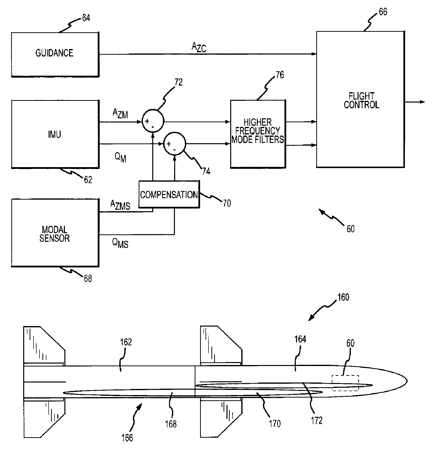
[0030]The present invention provides a simple and inexpensive mechanism to sense and mitigate the effects of flexible body dynamics on the flight control system for a flight vehicle without causing latency problems in the control loop. Modal sensors provide rate and possibly acceleration information for at least one flexible body mode of the flexible airframe component, suitably at least the 1st lateral bending mode for both pitch and yaw, so that the data provided to the flight controller more closely represents only the rate and acceleration of the flight vehicle's rigid airframe component, particularly at frequencies at or below the flight control bandwidth. Piezoelectric sensors can be configured to sense the strain induced by particular flexible body modes without inducing additional phase loss in the control loop. As sensor technology continues to advance, other known or new technologies may also provide the capability to sense these flexible body modes without phase loss. Thi...


PUM


Abstract

A flight control system is provided with one or more modal sensors that are each configured to measure the rate and possibly acceleration for a flexible body mode of the flight vehicle. The modal sensor's rate and suitably acceleration are subtracted from the rate and acceleration measured by the IMU such that the values provided to the flight controller more closely represent only the rate and acceleration of the flight vehicle's rigid airframe component. A piezoelectric modal sensor is capable of sensing a particular flexible body mode over variations in the modal frequency without inducing additional phase loss in the control loop in order to maintain suitable phase and gain margins. Sensors are suitably provided for at least and possibly only the 1st lateral bending modes in the pitch and yaw channels.

Description

BACKGROUND OF THE INVENTION[0001]1. Field of the Invention[0002]This invention relates to flight control systems that mitigate the effects of flexible body dynamics on flight vehicles such as missiles.[0003]2. Description of the Related Art[0004]Missile flight control systems receive rate and acceleration measurements from an on-board Inertial Measurement Unit (IMU) and apply a flight control law to actuate control surfaces (e.g. fins) to effectuate a guidance command. The missile's airframe flexes as it translates through the air. These flexible body dynamics introduce an unwanted signal to the control loop response. The flight control system must be designed to compensate for these flexible body dynamics or the system could have self-exciting vibrations. In the case where these vibrations are not bounded, catastrophic structural damage and mission failure will occur. In the case where the vibrations remain finite, the additional frequency content in the actuator commands can lead ...

Claims


Application Information

Patent Timeline
Patent Type & Authority Patents(United States)
IPC IPC(8): G05D1/00B64C13/16
CPCG05D1/107
Inventor ADAMS, ROBERTSCHWIND, WILLIAM
Owner RAYTHEON CO
Why Eureka
Try Eureka