Dual higher harmonic control (HHC) for a counter-rotating, coaxial rotor system

a rotor system and coaxial technology, applied in the field of rotary wings, can solve the problems of increasing maintenance and operating costs, contributing to crew fatigue, periodic aerodynamic load on the rotor blades, etc., and achieve the effect of reducing or theoretically eliminating airframe vibration

Active Publication Date: 2010-01-19
SIKORSKY AIRCRAFT CORP
View PDF12 Cites 42 Cited by
  • Summary
  • Abstract
  • Description
  • Claims
  • Application Information

AI Technical Summary

Benefits of technology

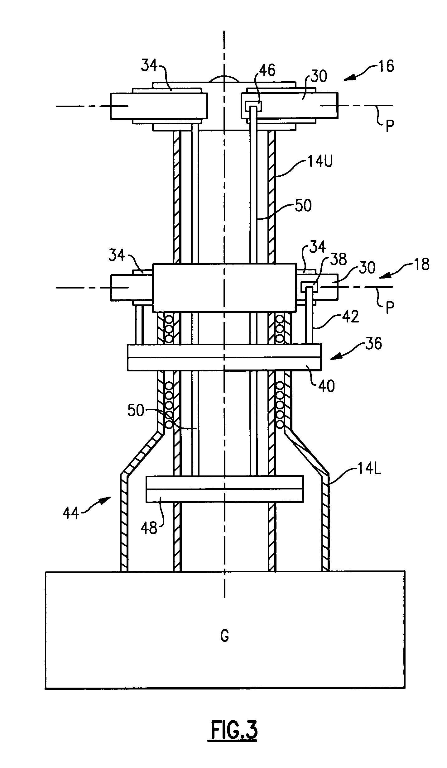
[0009]A dual, counter-rotating, coaxial rotor control system provides individual control of the upper rotor system and the lower rotor system. The lower rotor control system and the upper rotor control system provide six controls or “knobs” to minimize or theoretically eliminate airframe vibration. The current invention is based upon the key realization that the two rotors enable a total of six independent HHC controls which is equal to the number of vibratory hub loads created by two co-axial rotors in forward flight. For a vehicle equipped with co-axial rotors, the vibration from the two rotors combine to produce only six vibratory hub loads at the point where the rotor support shaft attaches to the aircraft. Thus, applying HHC to the two rotors can yield six independent controls to completely suppress six hub loads.

Problems solved by technology

Such vibrations may contribute to crew fatigue, increased maintenance, and operating costs.
A major cause of such vibrations is periodic aerodynamic loads on the rotor blades.
Reducing rotor-blade induced vibrations in a dual, counter-rotating, coaxial rotor system is further complicated as control inputs to the upper rotor control system and lower rotor control system are typically linked or slaved.
Such linkage may be acceptable to minimize vibrations to a certain extent but will not provide the more significant vibration reduction levels demanded by current rotary-wing aircraft operators.

Method used


Image

  • Dual higher harmonic control (HHC) for a counter-rotating, coaxial rotor system
  • Dual higher harmonic control (HHC) for a counter-rotating, coaxial rotor system
  • Dual higher harmonic control (HHC) for a counter-rotating, coaxial rotor system

Examples


Embodiment Construction

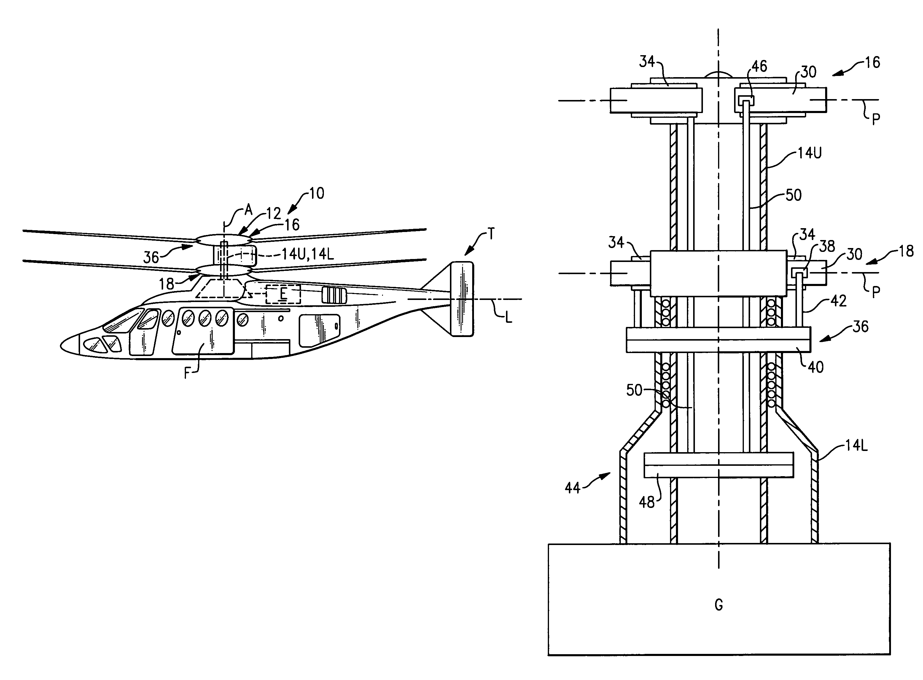
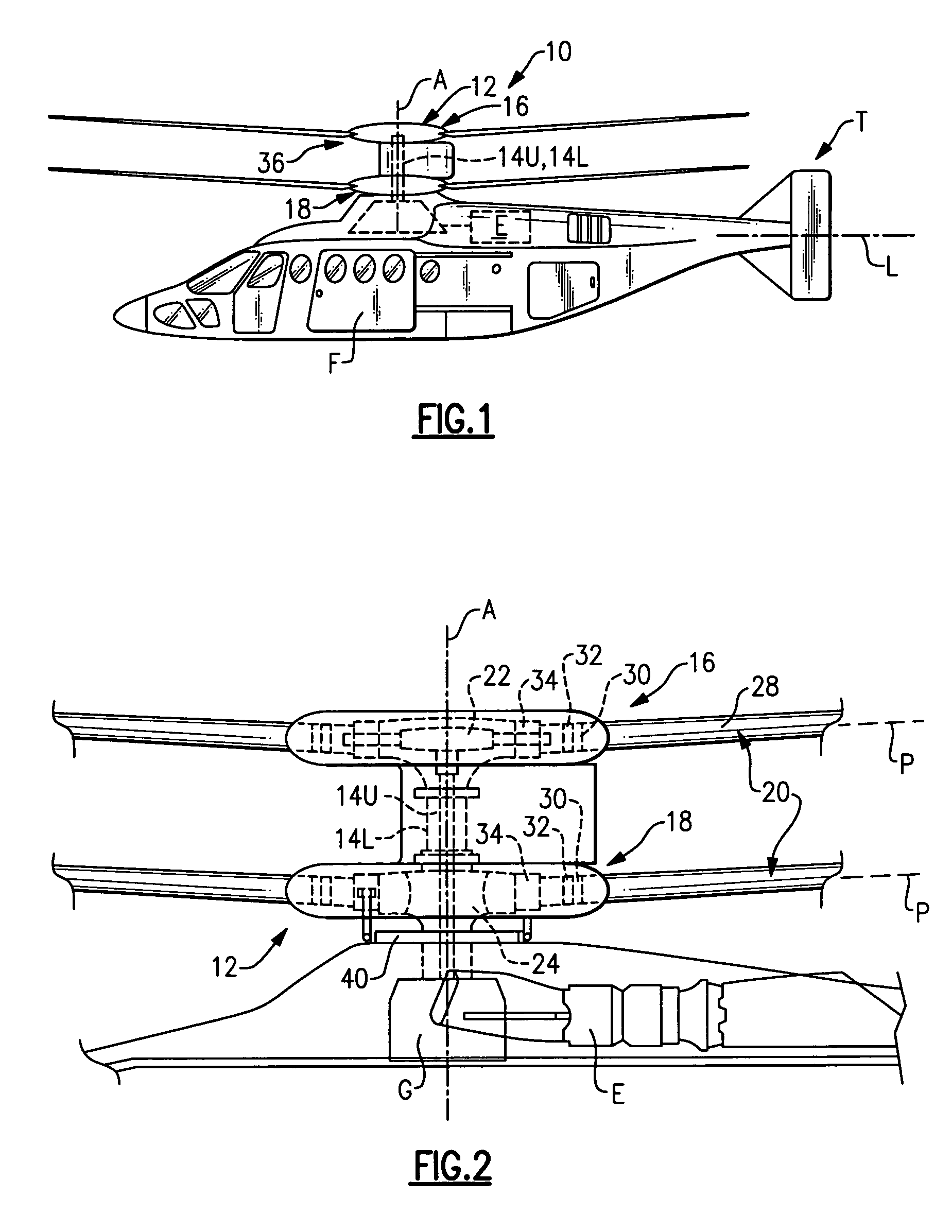
[0018]FIGS. 1 illustrates an exemplary vertical takeoff and landing (VTOL) rotary-wing aircraft 10 having a dual, counter-rotating, coaxial rotor system 12 which rotates about a rotating main rotor shaft 14U, and a counter-rotating main rotor shaft 14L (FIG. 2) both about an axis of rotation A. The aircraft 10 includes an airframe F which supports the dual, counter rotating, coaxial rotor system 12 as well as an optional translational thrust system T which provides translational thrust during high speed forward flight generally parallel to an aircraft longitudinal axis L. Although a particular aircraft configuration is illustrated in the disclosed embodiment, other counter-rotating, coaxial rotor systems will also benefit from the present invention. Although a particular counter-rotating, coaxial rotor system aircraft configuration is illustrated in the disclosed embodiment, other rotor systems and other aircraft types such as tilt-wing and tilt-rotor aircraft will also benefit from...


PUM


Abstract

A dual, counter-rotating, coaxial rotor system provides individual control of an upper rotor system and a lower rotor system. The lower rotor control system and the upper rotor control system provide six controls or “knobs” to minimize or theoretically eliminate airframe vibration. In a dual, counter-rotating, coaxial rotor system, application of a HHC system to the two rotor systems individually but located on the common axis, will yield essentially complete vibration reduction because the 6 controls will suppress the 6 loads.

Description

BACKGROUND OF THE INVENTION[0001]The present invention relates to a rotary-wing aircraft, and more particularly to a HHC vibration control system therefor.[0002]The reduction of vibrations is a primary goal in rotary-wing aircraft design. Such vibrations may contribute to crew fatigue, increased maintenance, and operating costs. A major cause of such vibrations is periodic aerodynamic loads on the rotor blades.[0003]An effective method of reducing rotor-blade induced vibrations is to control the harmonic airload at the source, i.e. on the rotor blades. For an N-bladed rotor, harmonic loads at a frequency rate of (N−1) per revolution, N per revolution and (N+1) per revolution are transmitted to the rotor hub. All three harmonic load frequencies in the rotating rotor frame of reference result in fuselage vibration in the non-rotating frame of reference at the frequency rate of N / revolution (hereinafter NP). The function of HHC devices is to generate additional airloads on the rotor so...

Claims


Application Information

Patent Timeline
Patent Type & Authority Patents(United States)
IPC IPC(8): B64C27/00
CPCB64C27/001B64C27/10B64C2027/7233B64C2027/7238Y02T50/34Y02T50/30
Inventor WELSH, WILLIAM A.
Owner SIKORSKY AIRCRAFT CORP
Why Eureka
Try Eureka