Method and apparatus for remotely operating AC powered appliances from video interphones or shopping terminals

a technology of video interphones and shopping terminals, applied in data switching networks, high-level techniques, instruments, etc., can solve the problems of high cost of ac electrical wiring customizing, inability to positively verify the on-off power status, and high cost of on-off switching devices, so as to simplify e-commerce shopping and low cost

Active Publication Date: 2010-01-19
ELBEX VIDEO LTD
View PDF8 Cites 130 Cited by
  • Summary
  • Abstract
  • Description
  • Claims
  • Application Information

AI Technical Summary

Benefits of technology

[0012]The apparatus for remotely operating AC powered appliances and other objects of the present invention are attained by an add on devices comprising wired, IR or RF receivers including AC power relays for receiving one way operational commands to operate the electrical appliances and / or wired, IR or RF transceivers including AC power relay and AC current sensors for receiving one way operational command to operate the electrical appliances and for transmitting on-off status signals from the appliances, in response to the received operational command or in response to an inquiry command (a request for status data) on the basis of the current sensor output, thereby providing error free remote controlling of the electrical home appliances.
[0014]The method of adding packaged relays and / or current sensors interfaces to an existing standard electrical switches and outlets instead of replacing them, introduces several major advantages; one is the lowering of the overall cost of the switches and outlets, because standard low cost, mass produced switches and outlets can be used. The second advantage is that the “add on devices” provide dual operation, manual operation via the commonly used switches and outlets on one hand and remote operation, in parallel with manual operation, via the relays of the add on devices. These advantages are the other objects of present invention, attained with total harmony and with no conflict between the manual and remote switching operation as described further below.
[0015]Another practical objective attained by the present invention is the freedom to select any from the wide variety of AC switches and outlets along with any of the extensive decorative covers and frames including variety of design and colors that are available and are being regularly introduced to the construction / electrical industry. Hence, this invention solves the persisting difficulties to match such wide range of available AC switches and outlets designs, their panel colors and decorations, particularly in a situation when a single home automation AC switch or an AC outlet is introduced but does not match the design or the color of a standard selected switches or AC outlets, that are installed into a multi gang switches / outlets setup.

Problems solved by technology

Most of the remote control devices, including IR or wireless remote control devices use the same power key to switch the appliance on and off, therefore without the operating person's self verification on site, with most of currently available remote control devices it is impossible to positively verify the on-off power status without being at the appliance site.
The problem such system represents is the cost for customizing of the AC electrical wiring, coupled with the on-off switching devices which are expensive and require expertise to configure, install and setup.
Therefore, the introduction of home automation devices calls for replacing the hardwired, the commonly used electrical AC switches and the AC outlets for transforming the basic standard electrical wiring, such as used for lighting, into a sophisticated operating systems that require maintenance and interventions by experts to repair or update, which is troublesome and costly.
The testing and approval processes are costly and time consuming, which makes approvals of customs designed AC electrical switches, AC electrical outlets and AC electrical interfaces for home automation out of reach to the mass market, limiting the proliferation of the much needed home automation to only custom designed AC switches, outlets and interfaces, for use in very expensive homes.
The problem however for such remote controlling is the need for a verified on-off status of the appliances being operated and / or the availability of a status report covering all the remotely controlled appliances of a given house, office, apartment or a building.

Method used


Image

  • Method and apparatus for remotely operating AC powered appliances from video interphones or shopping terminals
  • Method and apparatus for remotely operating AC powered appliances from video interphones or shopping terminals
  • Method and apparatus for remotely operating AC powered appliances from video interphones or shopping terminals

Examples


Embodiment Construction

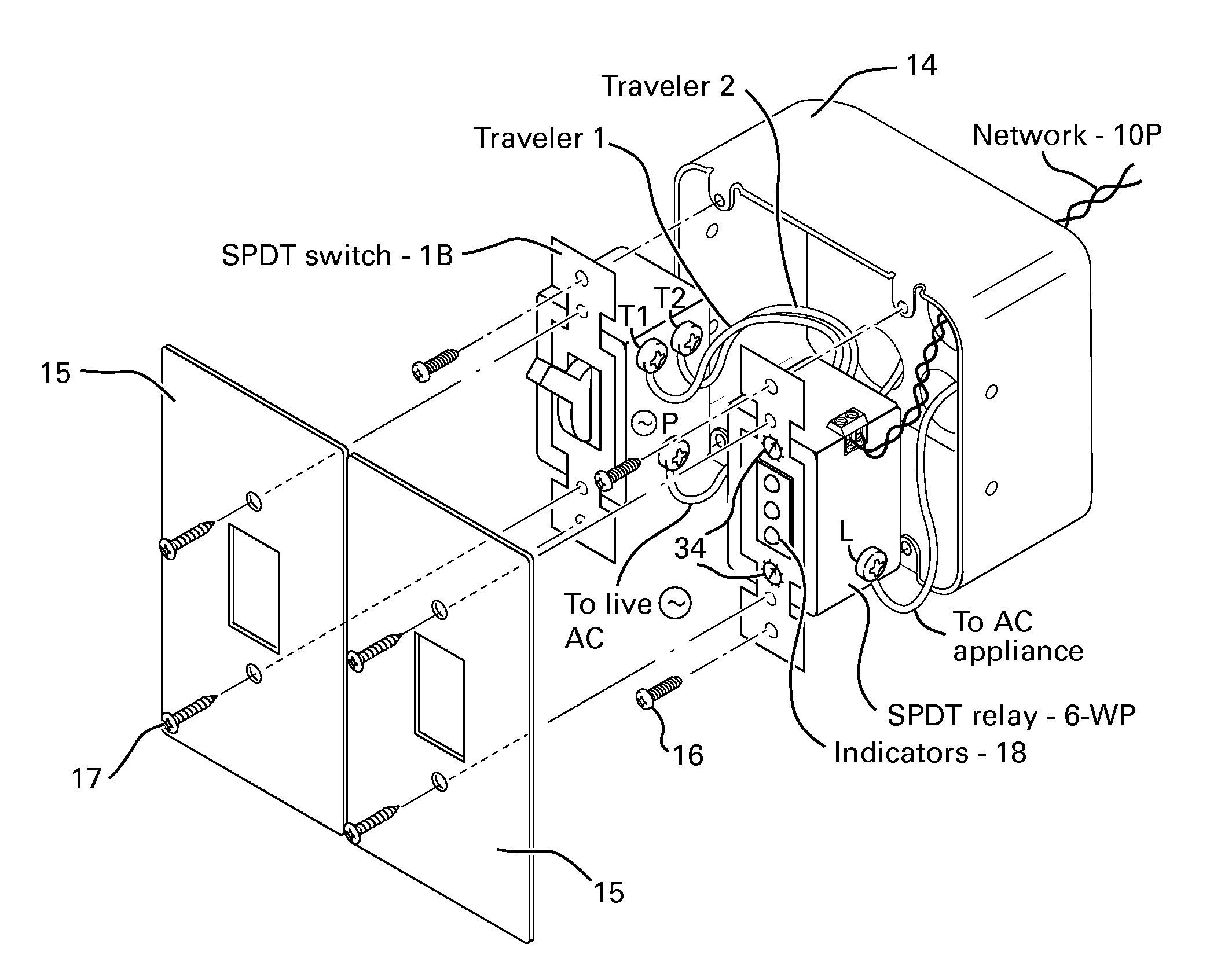
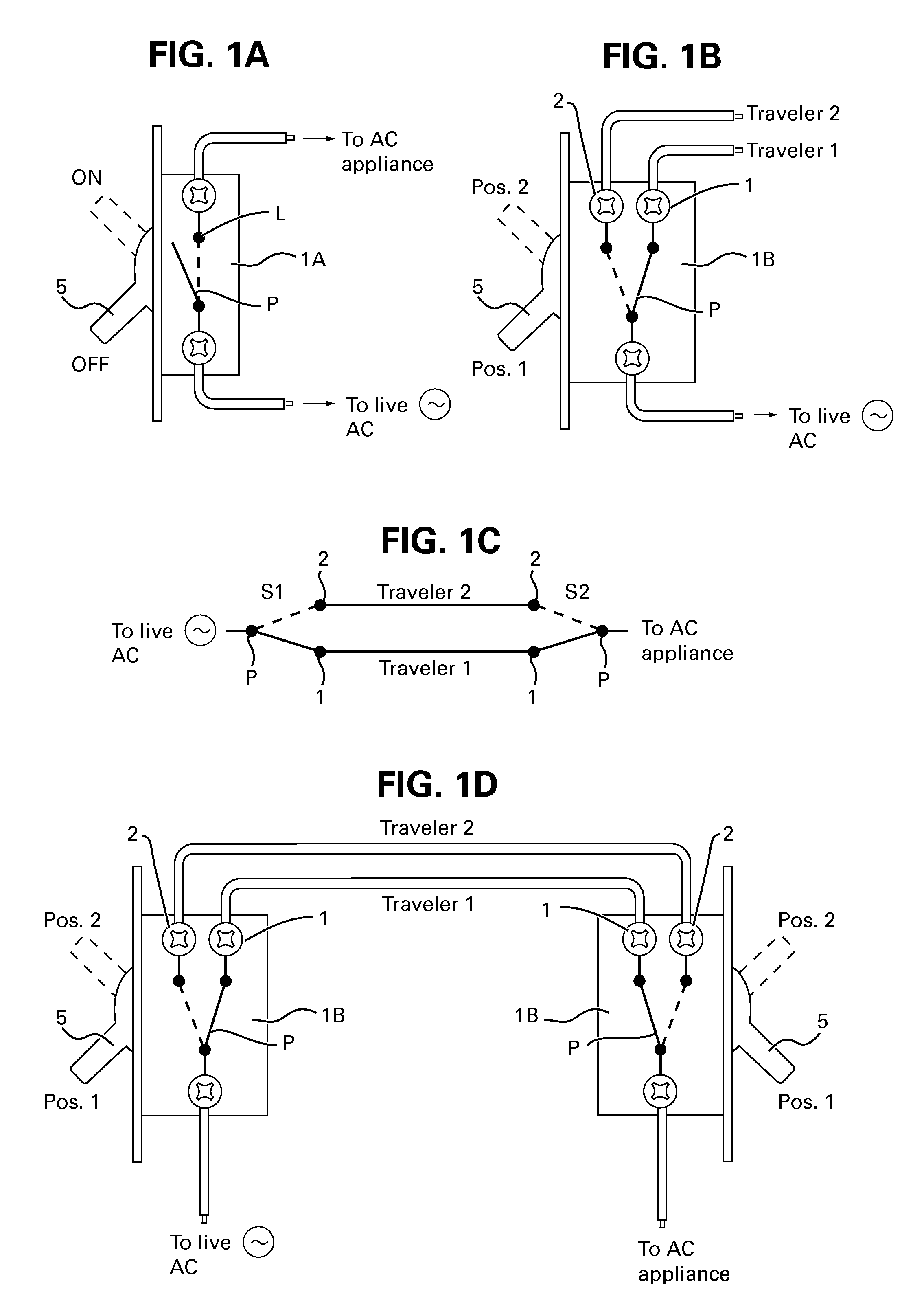
[0043]Shown in FIG. 1A is a standard on-off switch 1A used for operating AC appliances including appliances such as light fixtures, air conditioners and any other electrical devices that are operated by AC power. The standard on-off switch 1A is known as single pole-single throw (SPST) switch that includes lever activated spring contacts for making (on state) or breaking (off state) the electric circuit carrying AC current to the appliance. Remotely operated switch used for home automation is in fact a relay activated contacts (not shown) for making or breaking the AC current fed to an AC appliance, similar to the switch 1A of FIG. 1A.

[0044]For error free remote switching of the appliance it is necessary to know the appliance on or off status. It is possible to know the on or off status when using remotely operated SPST relay, on the basis of the data fed to the relay driver circuit, such as the driver 36 shown in FIG. 11A, which may be a driver transistor or IC. There is however a ...


PUM


Abstract

A method for adding and connecting a remotely operated SPDT relay to an electric power circuit of an AC appliance connected to a manually actuated electrical SPDT switch for integrating said AC appliance into an home automation network, each said relay and said SPDT switch includes a pole terminal and dual traveler terminals and said relay is similar to a shape and a size of an AC switch fit for installation into a standard electrical box.

Description

BACKGROUND OF THE INVENTION[0001]1. Field of the Invention[0002]This invention is related to video interphone system and to wired or wireless control, including IR and RF, used for remotely operating AC switches and AC powered electrical devices and appliances.[0003]2. Description of the Prior Art[0004]Wired or wireless remote control devices including InfraRed (IR) or RF transmitter for remotely operating AC powered electrical appliances such as television receivers, home heaters, air conditioners, motorized curtains, lighting and other electrical appliances in homes, apartments, offices and buildings in general are switched on and off by a one way control or command signal, with the person operating the remote control device verifying the on or off status of the operated device by visual means, such as the TV is on, or the lights are off, or the aircondition unit is activated or not, by being at the site of the operated appliance. Most of the remote control devices, including IR o...

Claims


Application Information

Patent Timeline
Patent Type & Authority Patents(United States)
IPC IPC(8): H01H47/22
CPCH01H9/167H04L12/12H04L12/2816G01R31/2825H01H2300/03H02J13/0075Y02B90/224Y04S20/14Y02B70/3241Y04S20/227Y02B70/325Y02B90/2653Y02B60/34Y04S20/228Y04S40/126H01H9/168H02J13/00024H02J13/00026H02J13/00036Y02B70/30Y02B90/20Y02D30/50Y04S20/20Y04S10/18Y02E60/00
Inventor ELBERBAUM, DAVID
Owner ELBEX VIDEO LTD
Why Eureka
Try Eureka