
Method of subnet roaming within a network

a subnet and network technology, applied in the field of wireless communications, can solve the problems of inefficient routing, large latencies in data traffic routing over the tunnel, and several limitations in the approach

Active Publication Date: 2010-01-19
HITACHI ENERGY LTD
View PDF17 Cites 36 Cited by
  • Summary
  • Abstract
  • Description
  • Claims
  • Application Information

AI Technical Summary

Benefits of technology

Enables efficient and scalable wireless handoffs across subnets, maintaining network connectivity and performance for mobile devices, reducing latency and overhead, and supporting nomadicity and mobility without the need for specialized client device hardware or software.

Problems solved by technology

This approach requires a centralized control which makes it non-scalable.
Additionally, routing can be inefficient.
This approach has several limitations.
Therefore, considerable latencies may be incurred in routing the data traffic over the tunnel.
In particular, this means that applications with low latency requirements such as voice or video will not be well served by this approach.
This also approach suffers from a “triangle routing problem”.
That is, if the Home Agent is not on the direct path between the Correspondent Host (CH) and the FA, then data traffic between the CH and the MN will travel a circuitous path, resulting in increased latencies and traffic inefficiencies.
In the case of TCP sessions, these lost packets may trigger a Slow Start / Congestion Avoidance phase that leads to dramatically reduced end-to-end throughput.
While this approach may be expected to work sufficiently well for macro-mobility scenarios, the overhead of routing traffic through a tunnel may be overkill for a situation where a mobile device is roaming quickly within a small geographic area (micro-mobility).
Generally, mesh networks suffer from the same handoffs limitations as the mobile phone system.

Method used


Image

  • Method of subnet roaming within a network
  • Method of subnet roaming within a network
  • Method of subnet roaming within a network

Examples


Embodiment Construction

[0027]As shown in the drawings for purposes of illustration, the invention is embodied in an apparatus and method for wireless roaming between subnets within a wireless mesh network.

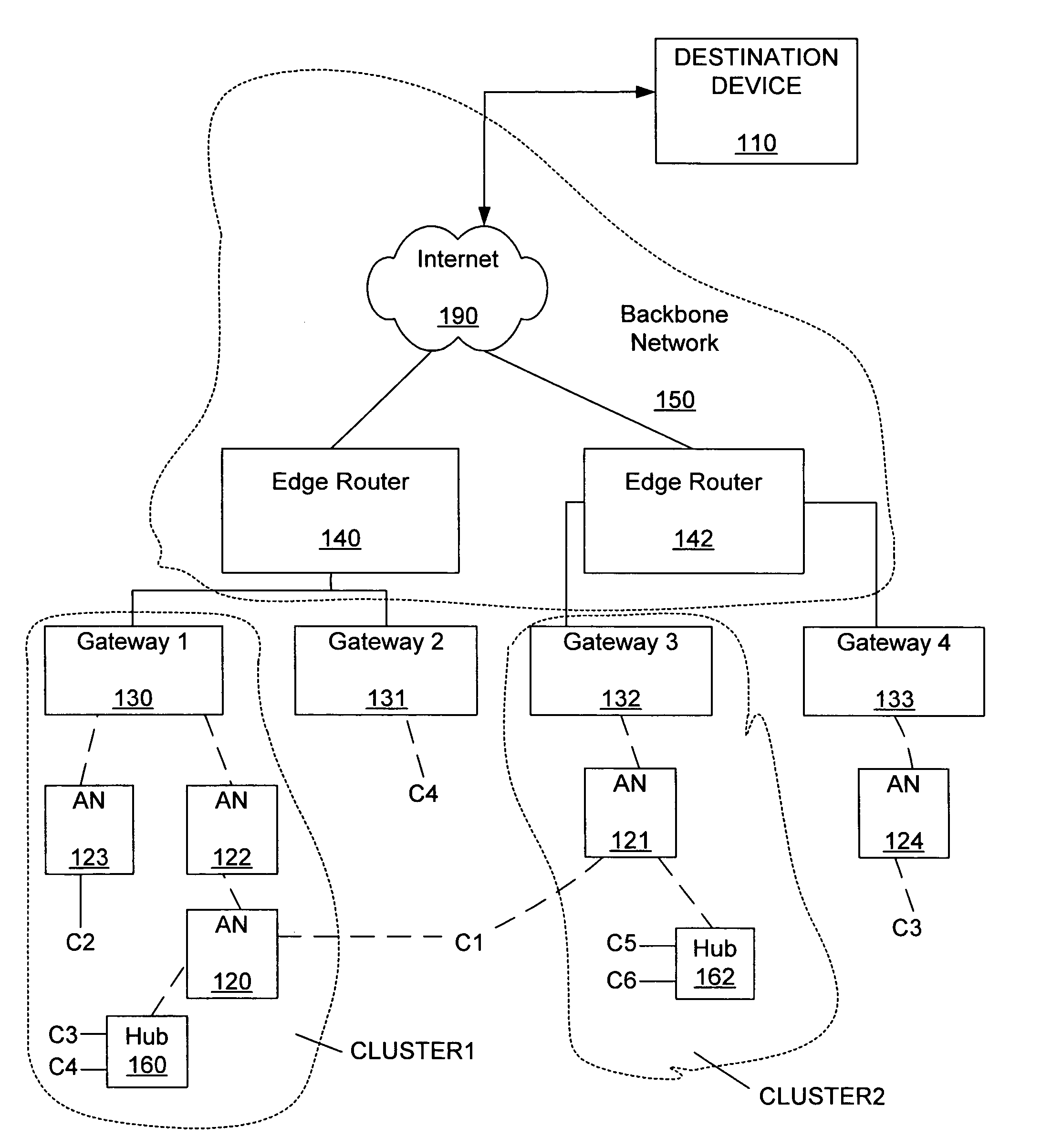
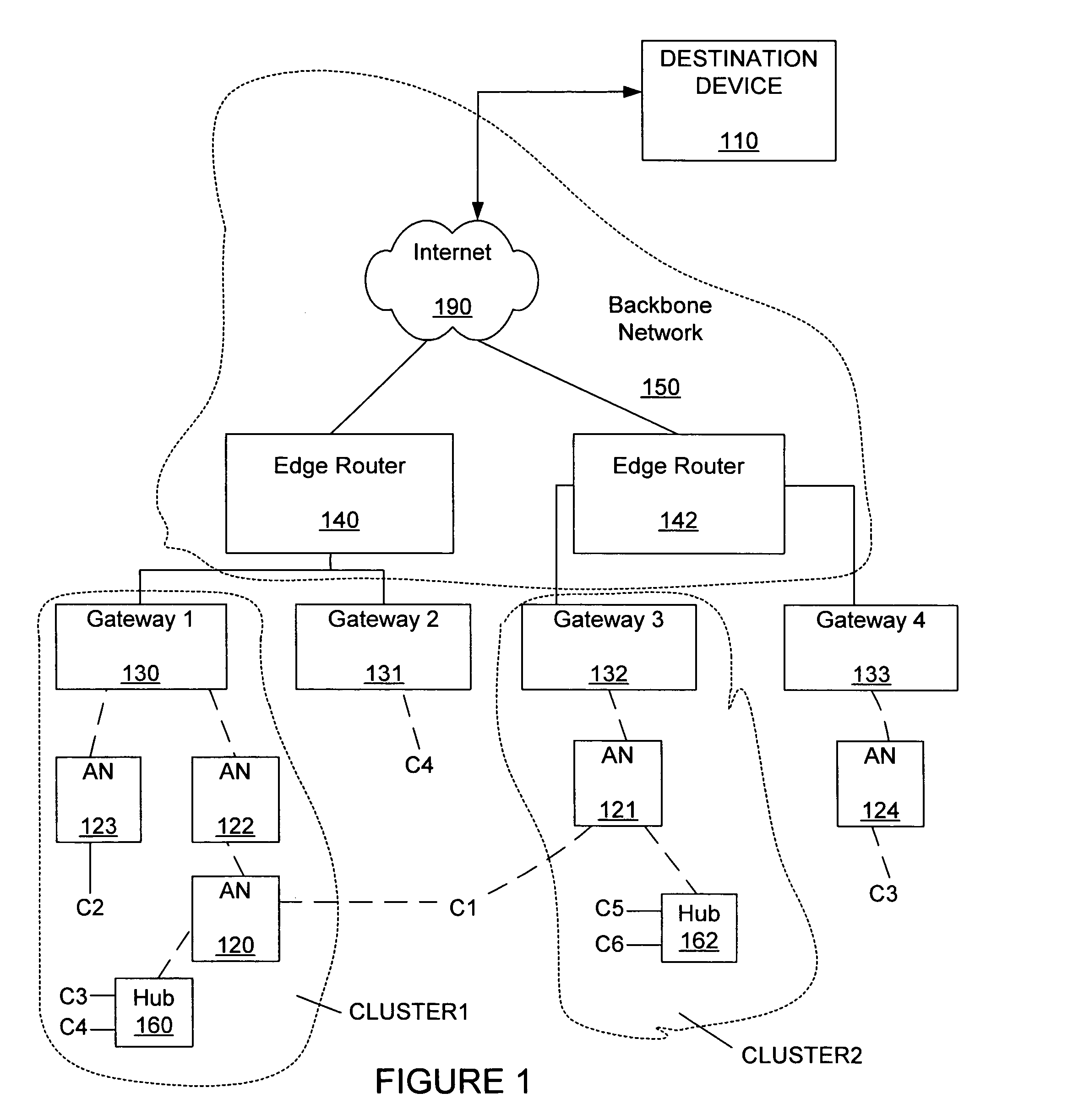
[0028]FIG. 1 shows a wireless mesh network that can include embodiments of the invention. Generally, the invention includes allowing a client C1 to communicate with a destination device 110, as the client C1 roams from wireless access with a first access node 120 to wireless access with a second access node 121. The wireless access nodes 120, 121 generally belong to a wireless mesh network.

[0029]The wireless mesh network as shown in FIG. 1 includes a first gateway 130, a second gateway 131, a third gateway 132 and a fourth gateway 133. Generally, the gateways 130, 131, 132, 133 are connected through wires to a first edge router 140 and a second edge router 142 of a backbone network 150. The edge routers 140, 141 provide wired connections to an internet network 190. The destination device 110 is connected...


PUM


Abstract

Disclosed is an apparatus and method of client device roaming from a home subnet to a foreign subnet of a network. The method includes the client device accessing the network through a first access node of the home subnet, and the client device roaming to a second access node of the foreign subnet, the client device accessing the network through the second access node, the client device maintaining a fixed client IP address, default gateway IP address and IP subnet attachment as the client device roams from the first access node to the second access node.

Description

RELATED PATENT APPLICATIONS[0001]This patent application is a continuation-in-part of patent application Ser. No. 10 / 602,179 filed on Jun. 24, 2003 now U.S. Pat. No. 7,016,328.FIELD OF THE INVENTION[0002]The invention relates generally to wireless communications. More particularly, the invention relates to a method of subnet roaming within a network.BACKGROUND OF THE INVENTION[0003]Packet networking is a form of data communication in which data packets are routed from a source device to a destination device. Packets can be networked directly between a source node and a destination node, or the packets can be relayed through a number of intermediate nodes.[0004]A wireless network can include a wireless device being connected to a network through a base station that is wired to the network. The wireless device can transmit data packets that are received by the base station and then routed through the network. The wireless network can include many base stations that are each wired to t...

Claims


Application Information

Patent Timeline
Patent Type & Authority Patents(United States)
IPC IPC(8): H04W4/00G06KH04L12/28H04L12/56H04L29/12H04W36/08H04W40/02H04W40/24H04W40/32H04W40/36H04W74/00H04W80/00H04W84/00H04W88/08H04W88/16
CPCH04L12/2856H04L29/12018H04L45/04H04L61/10H04L61/2015H04W40/02H04W80/00H04W40/246H04W40/248H04W40/32H04W40/36H04W84/00H04W88/08H04W88/16H04L61/5014
Inventor CHARI, AMALAVOYALSRIKRISHNA, DEVABHAKTUNIZHUGE, JOHN
Owner HITACHI ENERGY LTD
Learn More