Communication apparatus, communication system, communication method, and communication control program

a communication control and communication system technology, applied in the field of communication control programs, communication systems, communication methods, communication apparatuses, etc., can solve the problems of affecting and preventing an increase in throughput, so as to improve the efficiency of frame format and increase the effective throughput of communication

Active Publication Date: 2010-01-19
PALMIRA WIRELESS AG
View PDF42 Cites 42 Cited by
  • Summary
  • Abstract
  • Description
  • Claims
  • Application Information

AI Technical Summary

Benefits of technology

[0010]It is therefore required to solve the problem of overhead accompanying the transmission of a plurality of frames upon an improvement in the efficiency of a frame format and increase the effective throughput of communication.
[0011]Accordingly, the present invention is directed to provide a communication apparatus, communication system, communication method, and communication control program which can improve throughput by aggregating multiple MAC frames addressed to different destinations.

Problems solved by technology

In radio communication, since it is difficult for a communication apparatus to monitor transmission data while transmitting the data, media access control which is not premised on collision detection is required.
Even if an attempt to increase the communication speed in terms of physical layer succeeds, the effective throughput of communication cannot be improved.
An increase in overhead due to this may hinder an increase in throughput.
However, the overhead of a physical layer header and preamble cannot be effectively reduced.
However, since the length of a physical layer frame containing MAC frames cannot be increased beyond about 4 kbytes under the conventional limitation on the physical layer, an improvement in efficiency is greatly limited.
Even if the length of a PHY layer frame can be increased, another problem arises, i.e., a reduction in error tolerance.

Method used


Image

  • Communication apparatus, communication system, communication method, and communication control program
  • Communication apparatus, communication system, communication method, and communication control program
  • Communication apparatus, communication system, communication method, and communication control program

Examples


first embodiment

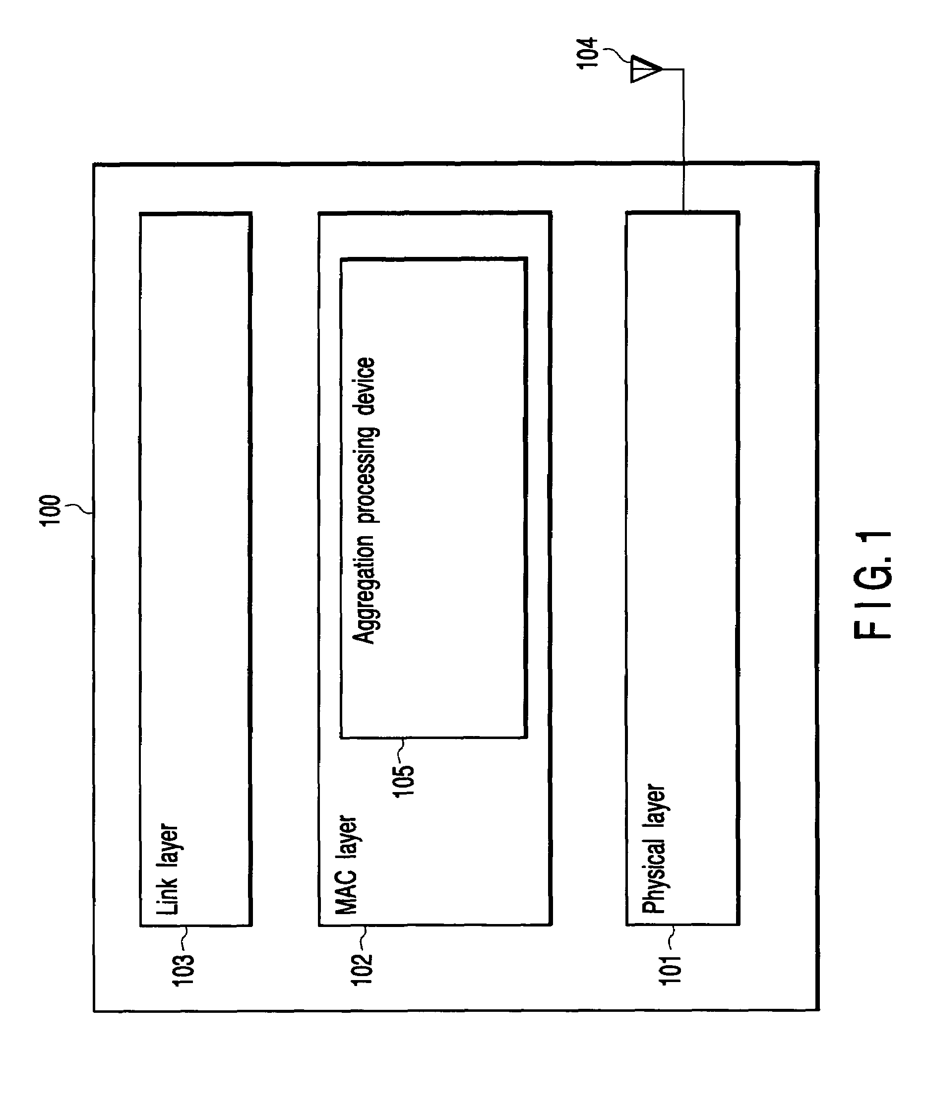
[0070]FIG. 1 is a block diagram showing the arrangement of a communication apparatus according to an embodiment of the present invention. A communication apparatus 100 is an apparatus configured to communicate with another communication apparatus through a radio link, and includes processing units 101, 102, and 103 respectively corresponding to a physical layer (PHY layer), MAC layer, and link layer. These processing units are implemented as analog or digital electronic circuits in accordance with implementation requirements. Alternatively, the processing units are implemented as firmware or the like to be executed by a CPU incorporated in an LSI. An antenna 104 is connected to the processing unit 101 corresponding to the physical layer. The MAC layer 102 includes an aggregation processing device 105 according to the present invention.

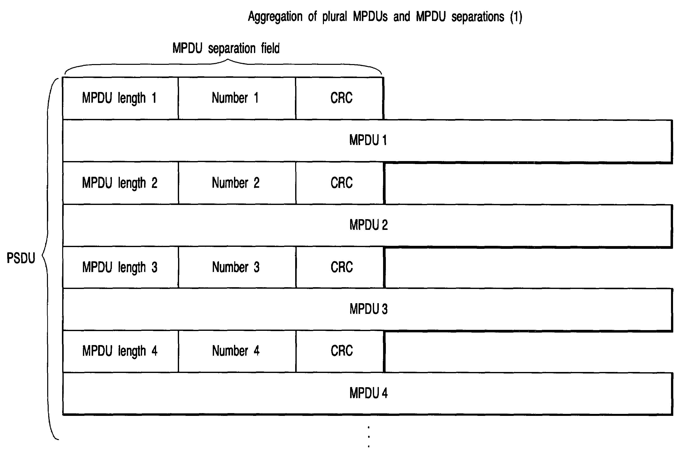
[0071]The aggregation processing device 105 generates a PHY (physical) frame containing a plurality of media access control (MAC) frames (MPDUs). MPDU...

second embodiment

[0100]In IEEE 802.11e standard, several access control techniques designed to improve quality of service (QoS) are known. For example, according to HCCA, as a QoS technique of guaranteeing parameters such as a designated bandwidth or delay limit, scheduling is performed in a polling sequence in consideration of required quality. As a QoS technique according to the second embodiment of the present invention, HCCA is assumed which guarantees quality for each traffic stream. QoS in the IEEE 802.11e standard includes DCF (Distributed Coordination Function), PCF (Point Coordination Function), EDCA (Enhanced Distributed Channel Access), and HCCA (HCF Controlled Channel Access). HCCA is an extended scheme of conventional PCF used by an IEEE 802.11 AP to perform polling control. In HCCA, a QoS-AP is called a HC (Hybrid Coordinator). The HC performs bandwidth management including the allocation of TXOPs (transmission opportunities) to QoS station.

[0101]As shown in FIG. 14, when communication...

third embodiment

[0134]The third embodiment of the present invention is directed to a communication apparatus which transmits many Block Ack control frames (BlockAckReq / BlockAck for each TS) defined in IEEE 802.11e upon containing them in one physical frame. IEEE 802.11e defines Block Acks which are transmitted at SIFS intervals in a burst manner. A communication sequence using Block Acks can be executed even in a case wherein the frame aggregation described above is not performed.

[0135]In this embodiment, a Block Ack Request frame for different destinations is simulcasted as in the first and second embodiments. In addition, as in the first and second embodiments, Block Ack frames are transmitted with time lags to avoid collision between the response frames.

[0136]FIG. 22 shows the frame sequence using Block Acknowledgement defined in IEEE 802.11e. The frame sequence shown in FIG. 22 exemplifies the case of immediate Block Ack. A Block Ack sequence includes two schemes: an immediate type in which whe...


PUM


Abstract

A communication apparatus includes a physical frame generating device configured to generate a single physical frame which includes a plurality of media access control frames having different destinations and in which frames, of the media access control frames, which have the same destination are consecutively arranged, and a transmitting device configured to transmit the physical frame generated by the physical frame generating device.

Description

CROSS-REFERENCE TO RELATED APPLICATIONS[0001]This application is based upon and claims the benefit of priority from prior Japanese Patent Applications No. 2004-110446, filed Apr. 2, 2004; and No. 2004-180226, filed Jun. 17, 2004, the entire contents of both of which are incorporated herein by reference.BACKGROUND OF THE INVENTION[0002]1. Field of the Invention[0003]The present invention relates a communication apparatus, communication system, communication method, and communication control program which perform media access control (MAC) and, more particularly, to frame aggregation for transmitting a plurality of media access control frames (MAC frames) upon containing them in one physical frame (PHY frame).[0004]2. Description of the Related Art[0005]Media access control (MAC) is control for causing a plurality of communication apparatuses which perform communication while sharing the same medium to decide how to use the medium in transmitting communication data or management frame...

Claims


Application Information

Patent Timeline
Patent Type & Authority Patents(United States)
IPC IPC(8): G08C25/02H03M13/00H04L1/18H04J3/24H04L12/28H04L47/43H04W28/06H04W84/12
CPCH04W99/00H04W28/06H04L2212/00
Inventor NISHIBAYASHI, YASUYUKITAKAGI, MASAHIROADACHI, TOMOKONAKAJIMA, TETSUUTSUNOMIYA, YORIKOTANDAI, TOMOYA
Owner PALMIRA WIRELESS AG
Why Eureka
Try Eureka