Low-delayed luminescence dense and rapid scintillator material

a scintillator and luminescence dense technology, applied in the field of scintillator materials, can solve the problems of poorer ct resolution, inability to achieve afterglow, and inability to meet the requirements of the application,

Active Publication Date: 2010-01-26
LUXIUM SOLUTIONS LLC
View PDF5 Cites 31 Cited by
  • Summary
  • Abstract
  • Description
  • Claims
  • Application Information

AI Technical Summary

Problems solved by technology

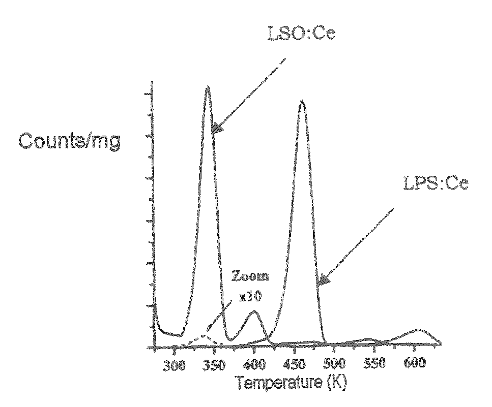
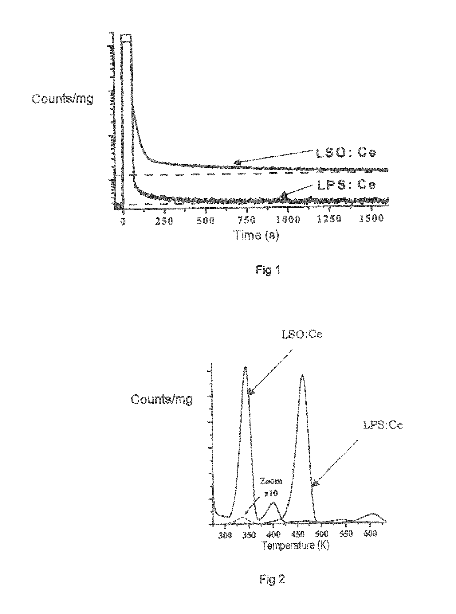
This phenomenon may be unacceptable in applications in which it is desired to isolate each pulse, using very short windowing.
When the CT system is coupled to a PET (Positron Emission Tomography) scanner, which is becoming the standard in industry, the poorer resolution of the CT affects the performance of the entire system and therefore the capability of the clinician to interpret the result of the complete PET / CT system.
Afterglow is known to be completely unacceptable for these applications.
However, compositions of the LPS type have the drawback of a lower stopping power than those of the LSO or LYSO type.

Method used


Image

  • Low-delayed luminescence dense and rapid scintillator material
  • Low-delayed luminescence dense and rapid scintillator material
  • Low-delayed luminescence dense and rapid scintillator material

Examples


examples

[0040]Three LYSO:Ce single crystals 1 inch in diameter were produced using the Czochralski method under conditions identical to those described in the aforementioned patents. To do this, raw materials corresponding to the following compositions were used:[0041]Control (with no Ca):[0042]Lu1.8Y0.1978Ce0.0022Si4.9961 [0043]Composition 1:[0044]Lu1.8Y0.1778Ca0.02Ce0.0022SiO4.9961 [0045]Composition 2:[0046]Lu1.8Y0.1878Ca0.01Ce0.0022SiO4.9961.

[0047]The charges were prepared from the corresponding oxides (Ca, Ce, Lu, Y oxides) so as to obtain the desired formulae. The actual Ce and Ca concentrations in the final crystal were lower than those introduced via the raw materials through segregation during crystal growth.

[0048]The single crystals finally obtained, of formula Lu(2−y)Y(y−z−x)CexCazSiO5, had the following compositions at the top of the specimen:

[0049]

Control (no Ca)Composition 1Composition 2x0.000260.000310.00036y0.0950.0950.095z00.000410.00023

[0050]Composition 1 gave a significant...


PUM

PropertyMeasurementUnit
energyaaaaaaaaaa
temperatureaaaaaaaaaa
thicknessaaaaaaaaaa

Abstract

The invention relates to an inorganic scintillator material of formula Lu(2−y)Y(y−z−x)CexMzSi(1−v)M′vO5, in which:M represents a divalent alkaline earth metal and M′ represents a trivalent metal, (z+v) being greater than or equal to 0.0001 and less than or equal to 0.2,z being greater than or equal to 0 and less than or equal to 0.2;v being greater than or equal to 0 and less than or equal to 0.2,x being greater than or equal to 0.0001 and less than 0.1; andy ranging from (x+z) to 1.In particular, this material may equip scintillation detectors for applications in industry, for the medical field (scanners) and / or for detection in oil drilling, The presence of Ca in the crystal reduces the afterglow, while stopping power for high-energy radiation remains high.

Description

CROSS-REFERENCES TO RELATED APPLICATIONS[0001]The present application is the U.S. counterpart of WO 2006 / 018586 filed Aug. 8, 2005, the text of which is incorporated by reference and claims the priority of the French application No. 04 / 51815, filed Aug. 9, 2004 the text of which is incorporated by reference.BACKGROUND OF THE INVENTION[0002]The invention relates to scintillator materials, to a manufacturing process for obtaining them and to the use of said materials, especially in gamma-ray and / or X-ray detectors.[0003]Scintillator materials are widely used in detectors For gamma rays, X-rays, cosmic rays and particles having an energy of the order of 1 keV and also above this value.[0004]A scintillator material is a material that is transparent. In the scintillation wavelength range, which responds to incident radiation by emitting a light pulse.[0005]It is possible to manufacture from such materials, which are generally single crystals, detectors in which the light emitted by the c...

Claims


Application Information

Patent Timeline
Patent Type & Authority Patents(United States)
IPC IPC(8): C09K11/77C09K11/08G01T1/20
CPCC09K11/745C09K11/7774G01T1/2023G21K4/00A61B6/4258C09K11/77742C09K11/77744
Inventor FERRAND, BERNARDVIANA, BRUNOPIDOL, LUDIVINEDORENBOS, PIETER
Owner LUXIUM SOLUTIONS LLC
Why Eureka
Try Eureka