
Luminescent material, especially for led application

a technology of led and light source, applied in the field of phosphor for light source, can solve the problems of poor color rendition of conjugated aluminates, insufficient position of excitation and emission bands of these aluminates, etc., and achieve the effects of high color rendering, efficient excitation of uv/blue radiation, and easy production

Active Publication Date: 2005-09-22
OSRAM OLED
View PDF9 Cites 108 Cited by
  • Summary
  • Abstract
  • Description
  • Claims
  • Application Information

AI Technical Summary

Benefits of technology

[0004] It is an object of the present invention to provide a new luminescent material. A further object is to provide a phosphor with a fine-tuned green emission which can be efficiently excited by UV / blue radiation. A further object is to provide a phosphor for use in an illumination device with at least one LED as light source, the LED emitting primary radiation in the range from 380 to 470 nm, this radiation being partially or completely converted into longer-wavelength radiation by such phosphors which are exposed to the primary radiation of the LED. A further object is to provide an illumination device which emits white light and in particular has a high color rendering. A further object is to provide a high-efficiency illumination device like a LED device which absorbs well in the range from 380 to 470 nm and is easy to produce.
[0006] The conversion is achieved at least with the aid of a phosphor which originates from the class of the Eu- or Eu,Mn-coactivated silicone oxynitrides. In more detail, a novel phosphor material is created by doping MSi2O2N2 (M=Ca, Sr, Ba) host lattices with Eu ions. The obtained phosphors show high chemical and thermal stability.
[0008] Preferably, the metal M is Ca or at least mainly Ca with minor additions of Ba and / or Sr for a green-emitting material which can be efficiently excited with blue radiation. The incorporation of nitrogen increases the degree of covalent bonding and ligand-field splitting. As a consequence this leads to a shift of excitation and emission bands to longer wavelengths compared to oxide lattices. The obtained phosphors show high chemical and thermal stability.

Problems solved by technology

Such a combination has a poor color rendition, which, however, can be improved significantly by using a red-green-blue system (RGB).
However, the position of the excitation and emission bands of theses aluminates is not optimum.

Method used


Image

  • Luminescent material, especially for led application
  • Luminescent material, especially for led application
  • Luminescent material, especially for led application

Examples


Embodiment Construction

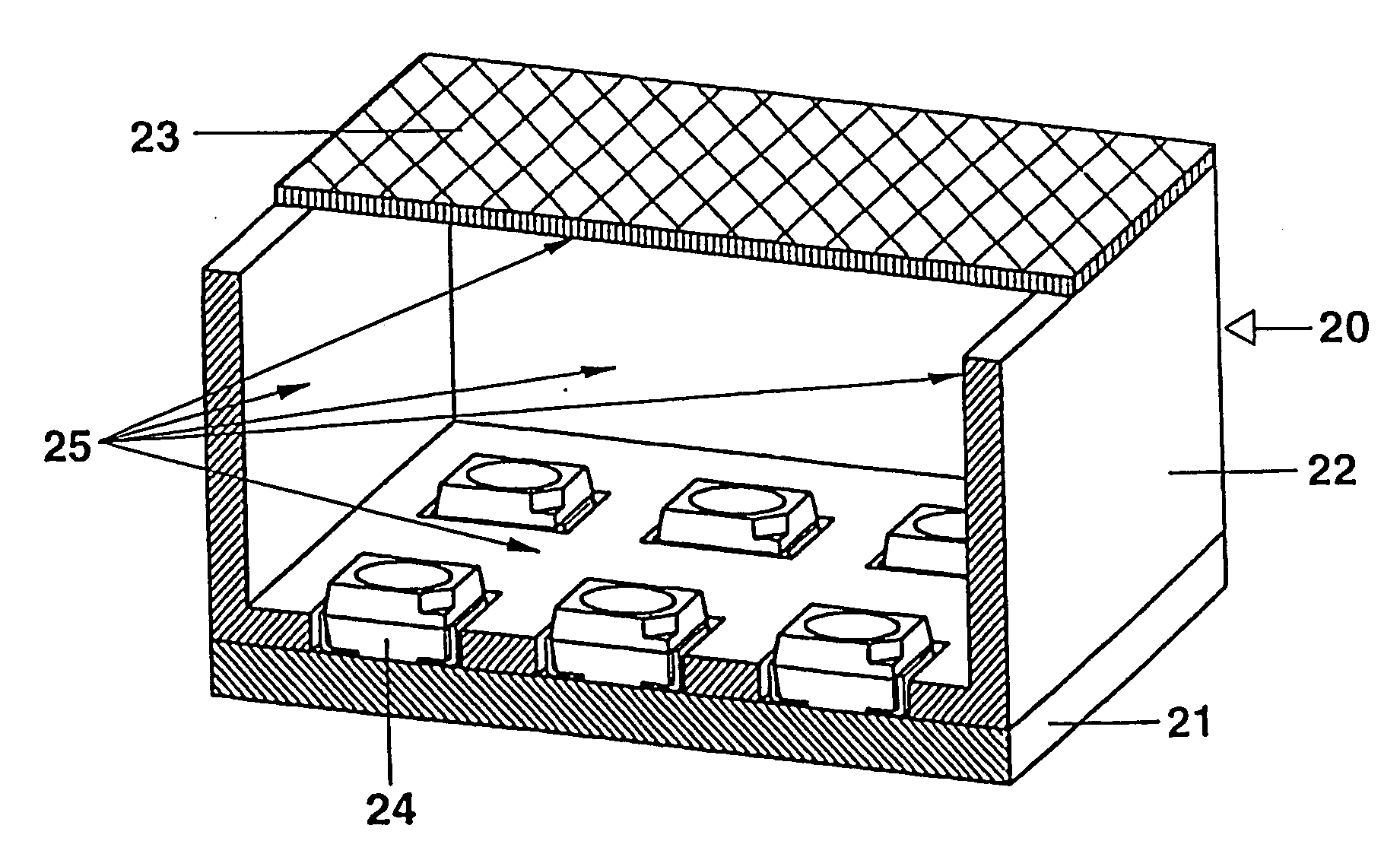
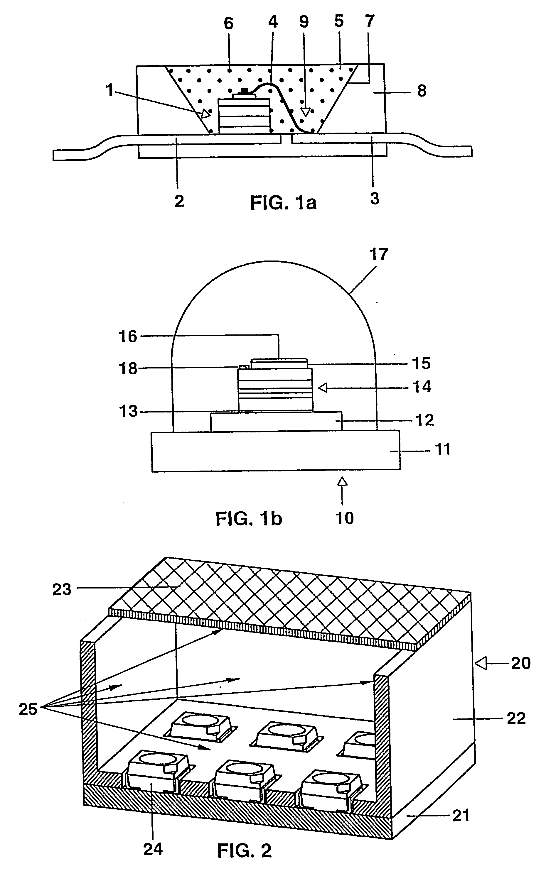
[0015] By way of example, a structure similar to that used in WO 01 / 40403 is described for use in a white LED together with an InGaN chip. The structure of such a light source for white light is specifically shown in FIG. 1a. The light source is based on a semiconductor component (chip 1) of type InGaN with a peak emission wavelength of 400 nm, having a first and a second electrical connection 2,3, which is embedded in an opaque base housing 8 in the region of a recess 9. One of the connections 3 is connected to the chip 1 via a bonding wire 4. The recess has a wall 7 which serves as reflector for the blue primary radiation of the chip 1. The recess 9 is filled with a potting compound 5 which contains a silicone casting resin (or epoxy casting resin) as its main constituents (pref. at least 80% by weight) and further comprises phosphor pigments 6 (pref. less than 15% by weight). There are also further small amounts of, inter alia, methyl ether and Aerosil. The phosphor pigments are ...


PUM

PropertyMeasurementUnit
Fractionaaaaaaaaaa
Fractionaaaaaaaaaa
Nanoscale particle sizeaaaaaaaaaa

Abstract

UV-blue excitable green luminescent material including an Eu-doped oxynitride host lattice with general composition MSi2O2N2, wherein M is at least one of an alkaline earth metal chosen from the roup Ca, Sr, Ba.

Description

TECHNICAL FIELD [0001] This invention relates to a luminescent material which is excitable in the UV-blue part of the spectral region, and more particularly, but not exclusively to a phosphor for light sources, especially for Light Emitting Diodes (LED). The phosphor belongs to the class of rare-earth activated silicon oxynitrides. BACKGROUND ART [0002] So far white LEDs were realized by combining a blue-emitting diode with a yellow emitting phosphor. Such a combination has a poor color rendition, which, however, can be improved significantly by using a red-green-blue system (RGB). Such a system uses for example a red and blue emitter in combination with a green-emitting aluminate phosphor, like SrAl2O4:Eu or BaAl2O4:Eu, with the possible addition of Mn to Eu, whose emission maximum is around 520 nm, see U.S. Pat. No. 6,278,135. However, the position of the excitation and emission bands of theses aluminates is not optimum. They have to be excited by short UV in the range of 330 to 4...

Claims


Application Information

Patent Timeline
IPC IPC(8): C09K11/08C09K11/64C09K11/59C09K11/66C09K11/77C09K11/79H01L25/13H01L33/50H05B33/14
CPCC09K11/7734Y10S428/917H01L33/502H01L2224/32245H01L2224/48091H01L2224/48247H01L2224/73265C09K11/77347H01L2924/00014H01L2924/00012H01L2924/00
Inventor DELSING, ANNE CHARLOTTE ANTOINETTEHINTZEN, HUBERTUS T.LI, YUAN-QIANG
Owner OSRAM OLED
Learn More