Image forming apparatus

a technology of image forming and forming lines, applied in the field of image forming technology, can solve the problems of affecting the image formation of lines, and not being able to correct, so as to achieve favorable image formation and eliminate skew in synchronization between lines

Inactive Publication Date: 2010-01-26
CANON KK
View PDF9 Cites 5 Cited by
  • Summary
  • Abstract
  • Description
  • Claims
  • Application Information

AI Technical Summary

Benefits of technology

[0021]Having been conceived in light of the aforementioned problems, an embodiment is configured to eliminate or at least mitigate a skew in synchronization between lines and thus enable favorable image formation.
[0025]According to the present invention, a skew in synchronization between lines can be eliminated, thus enabling favorable image formation.

Problems solved by technology

For this reason, there is a limit with current IC-operated clock bands, and thus there is a problem that a skew of several μm caused by a skew in the synchronization between lines may not be corrected, even at the beginning of the optical scanning.
There is an additional problem that a skew may arise in image formation between lines due to static deviation information such as deviation in the scanning magnification, dynamic deviation characteristics such as fluctuations in temperature, deterioration of the apparatus caused by age, and so on.

Method used


Image

  • Image forming apparatus
  • Image forming apparatus
  • Image forming apparatus

Examples


first embodiment

[0036]Hereinafter, exemplary preferred embodiments of the present invention shall be described in detail with reference to the diagrams. However, it should be noted that the constituent elements denoted in the following embodiments are to be taken as examples only; the technical scope of the present invention is defined by the appended claims, and is not intended to be limited by the individual embodiments described hereinafter.

[0037](Configuration of Image Forming Apparatus)

[0038]FIG. 8 is a diagram illustrating an example of a schematic configuration of an image forming apparatus according to an embodiment of the present invention. The image forming apparatus is capable of producing a full-color image by superimposing toner images of four colors, or yellow, cyan, magenta, and black, upon one another, using an electrophotographic method. Note, however, that the present invention is not intended to be limited to a color image forming apparatus; the present invention can of course be...

second embodiment

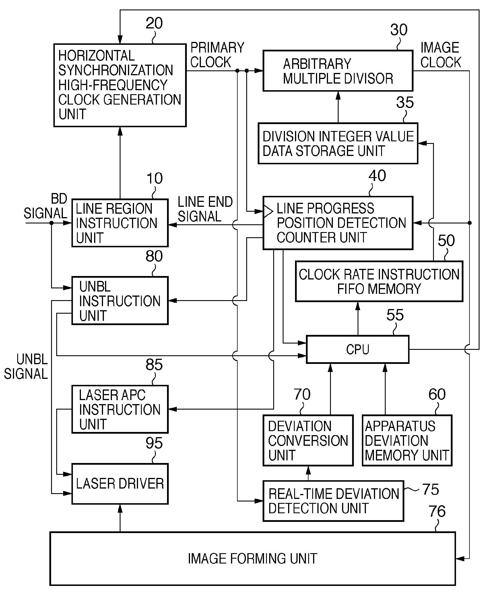
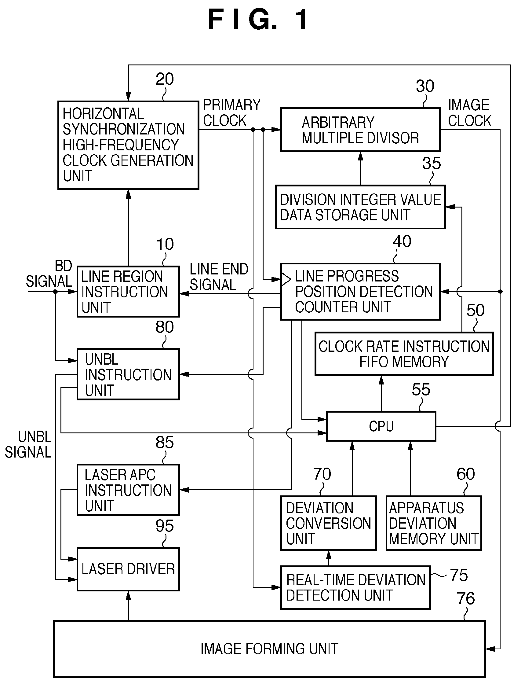
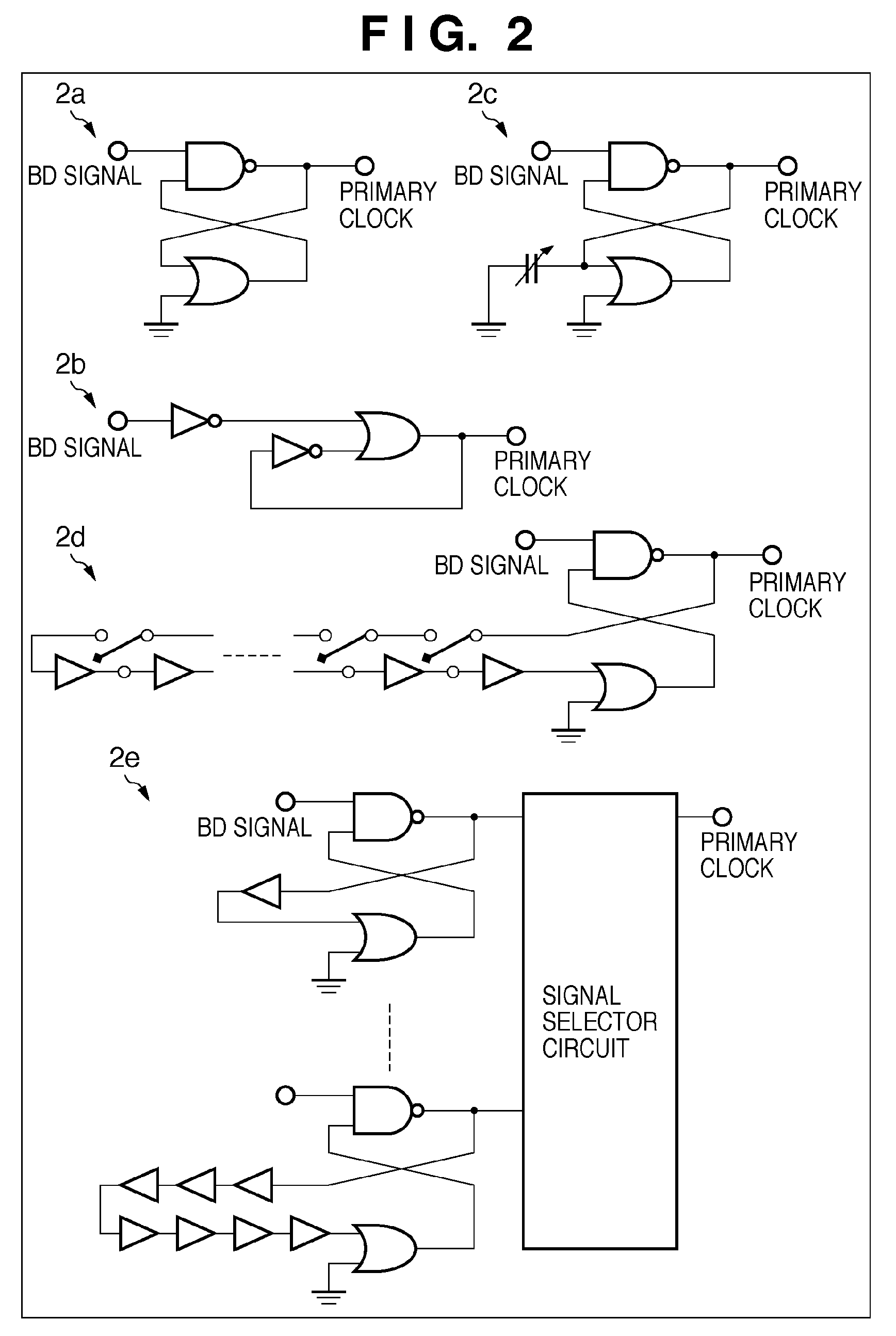
[0140]In the second embodiment, descriptions shall first be provided regarding the operations of a transport delay oscillator circuit unit 21, which is configured of a DLL circuit that utilizes the transport delay of the digital gate circuit found in the horizontal synchronization high-frequency clock generation unit 20 as configured in FIG. 2. Then, a frequency stabilizing correction unit for the primary clock, which is a characteristic of the present embodiment, shall be described with reference to FIG. 7.

[0141]FIG. 6 is a diagram illustrating an example of an operational timing, used to illustrate the characteristics of the DLL circuit, which in turn clearly illustrates the frequency stabilizing correction unit for the primary clock according to the present embodiment.

[0142]“6a” in FIG. 6 illustrates a specific example of the transport delay oscillator circuit unit 21 within the horizontal synchronization high-frequency clock generation unit 20 that generates the primary clock ba...


PUM


Abstract

In an image forming apparatus that outputs a reference clock, divides the outputted reference clock based on a set multiple, and generates an image clock based on the division, a width of a synchronization signal that indicates dynamic deviation characteristics is detected, and the multiple is set in accordance with the detected width of the synchronization signal.

Description

BACKGROUND OF THE INVENTION[0001]1. Field of the Invention[0002]The present invention relates to image forming technology.[0003]2. Description of the Related Art[0004]With a conventional image forming apparatus, such as a laser printer, a digital multifunction peripheral, or the like, that forms images using a laser beam scanning unit, images are formed using processes for increasing resolution, expressing multiple tones, smoothing, and so on, in order to achieve high image quality.[0005]As representative methods for increasing the quality of an image, there are methods, called pulse width modulation (abbreviated hereinafter as “PWM”), luminance modulation, and so on that are performed on the image data, in which the darkness and the like of dots are controlled by controlling the strength (performing strength control) of the amount of light irradiated onto a photosensitive member, on a pixel-by-pixel basis. In recent years, PWM and luminance modulation are being combined in an attem...

Claims


Application Information

Patent Timeline
Patent Type & Authority Patents(United States)
IPC IPC(8): B41J2/435B41J2/47
CPCG03G21/14
Inventor USHIO, YUKIHIDE
Owner CANON KK
Why Eureka
Try Eureka