
Robot and attitude control method of robot

a robot and attitude control technology, applied in the field of robots, can solve the problems of affecting the operation of the robot, the robot itself and/or the object that the falling robot collides with can be fatally damaged, and the robot itself and/or the object that the falling robot collides with can be suspended and other problems

Active Publication Date: 2010-02-02
SONY CORP +1
View PDF13 Cites 85 Cited by
  • Summary
  • Abstract
  • Description
  • Claims
  • Application Information

AI Technical Summary

Benefits of technology

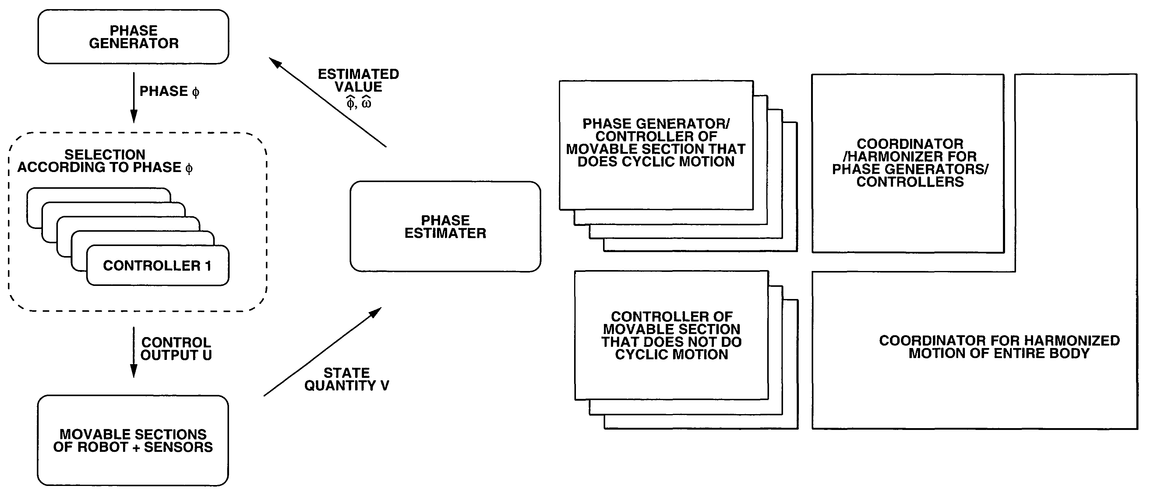
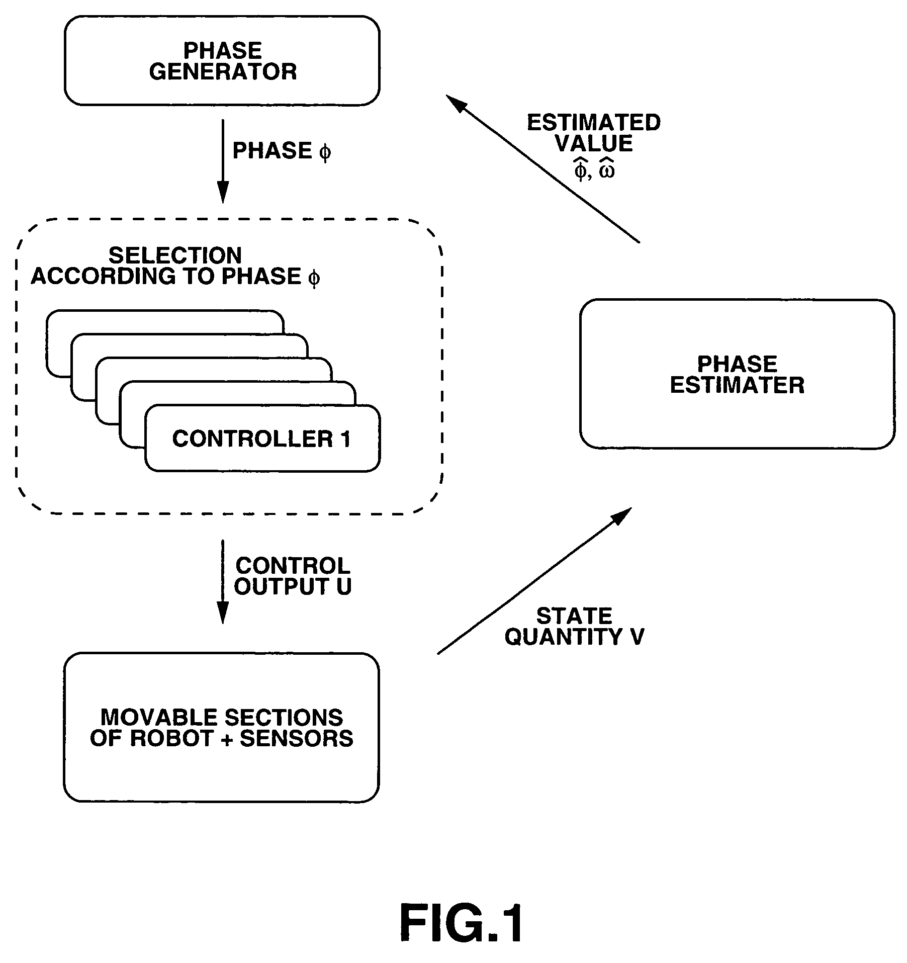
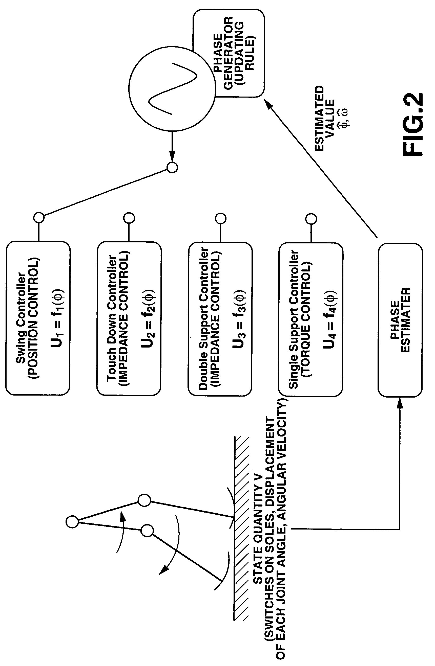
The present invention provides a robot that can autonomously maintain its stability and control the stability of its body without using a ZMP (zero moment point) as a stability criteria. The robot uses a phase signal generated by a phase generator to control the motion of its movable sections. The control means selects an appropriate controller based on the phase signal and the selected controller generates a control signal for the movable sections. The robot also detects the state quantities of the movable sections, estimates the phase and angular frequency of the periodic motion of the movable sections, and controls the drive of the movable sections accordingly. The invention provides a superior robot that can control its stability and motion by paying attention to periodic motions of its parts.

Problems solved by technology

When the body of a robot stumbles and falls, it means that the ongoing operation of the robot is suspended and that considerable power and time need to be spent for the robot to stand up from the failing state and resume its operation.
Additionally, when the robot stumbles and falls, there arises a risk that the robot itself and / or the object that the falling robot collides with can be fatally damaged.
Thus, the attitude / stability control of robots for avoiding stumbling and falling is one of the priority issues when developing two-legged mobile robots.
The standing posture of a robot that is based on human's biped locomotion is unstable as basic attitude.
In other words, stability control on that basis of a ZMP is accompanied by a problem of adaptability to unknown environment.
The operation of solving the ZMP equation entails a relatively heavy calculation cost and hence difficulties in real time control situations.
Then, as a result, neither a precise model nor a precise trajectory tracking control is required.
(Differently stated, if a precise model and a precise trajectory tracking control are required, the cost will rise due to the large gain and the precision).
However, the former document says that phase and frequency are entrained by a nonlinear differential equation (Matsuoka Oscillator) to reveal that it is not possible to obtain an analytic solution for the phase of the physical oscillator and hence mathematically design the system.
In short, it is not possible to get to any specific design theory.
However, it only describes regulation of the phase of the physical oscillator by way of an open loop immediately after a known external disturbance and lacks any feedback from the physical system and hence adaptability to unknown states and external disturbances.

Method used


Image

  • Robot and attitude control method of robot
  • Robot and attitude control method of robot
  • Robot and attitude control method of robot

Examples


Embodiment Construction

[0154]Now, the present invention will be described in greater detail by referring to the accompanying drawings.

A. Configuration of Robot

[0155]FIGS. 12 and 13 are schematic perspective front and rear views of a legged and standing mobile humanoid robot 100 that is an embodiment of the present invention. As illustrated, the legged mobile robot 100 has a trunk section, a head section, left and right upper limbs and left and right lower limbs that are driven to operate for moving. The operation of the machine body is controlled by a control section (not shown) that is typically contained in the trunk.

[0156]Each of the lower limbs has a thigh section, a knee joint, a shank section, an ankle and an instep and is linked substantially to the lower end of the trunk section by a hip joint. Each of the upper limbs has an upper arm, an elbow joint and a forearm and is linked to the corresponding upper lateral edge of the trunk section by a shoulder joint. The head section is linked substantiall...


PUM


Abstract

The motion of the movable sections of the robot is taken for a periodic motion so that the attitude of the robot can be stably controlled in a broad sense of the word by regulating the transfer of the movable sections. More specifically, one or more than one phase generators are used for the robot system and one of the plurality of controllers is selected depending on the generated phase. Then, the controller controls the drive of the movable sections according to continuous phase information. Additionally, the actual phase is estimated from the physical system and the frequency and the phase of the phase generator are regulated by using the estimated value, while the physical phase and the phase generator of the robot system are subjected to mutual entrainment so that consequently, it is possible to control the motion of the robot by effectively using the dynamics of the robot.

Description

BACKGROUND OF THE INVENTION[0001]1. Field of the Invention[0002]This invention relates to a robot having a plurality of movable sections such as legs and a method of controlling the attitude of such a robot. More particularly, the present invention relates to a robot that autonomously maintains the stability of its attitude according to a predetermined stability criteria and a method of controlling the attitude of such a robot.[0003]To be more specific, this invention relates to a robot that controls the stability of the attitude of its body without using a ZMP (zero moment point) as stability criteria and a method of controlling the attitude of such a robot. More particularly, it relates to a robot that controls the stability of the attitude of its body by paying attention to periodic motions of the moving parts thereof and a method of controlling the attitude of such a robot.[0004]This application claims priority of Japanese Patent Application No. 2003-300521, filed on Aug. 25, 20...

Claims


Application Information

Patent Timeline
Patent Type & Authority Patents(United States)
IPC IPC(8): B25J9/10G06F15/00G05B19/04G05B19/18B25J5/00B25J9/16B25J13/08B62D57/032
CPCB25J9/161B25J13/08B62D57/032G05B19/414Y10S901/01
Inventor ENDO, GENKAWATO, MITSUOCHENG, GORDONNAKANISHI, JUNMORIMOTO, JUN
Owner SONY CORP
Learn More