Carrier type conveying apparatus and conveying carrier connection system of the conveying apparatus

Active Publication Date: 2010-02-09
DAIFUKU CO LTD
View PDF19 Cites 16 Cited by
  • Summary
  • Abstract
  • Description
  • Claims
  • Application Information

AI Technical Summary

Benefits of technology

[0013]According to a conveying carrier connection system in the carrier type conveying apparatus according to the first aspect of the invention, in the rear-pushing traveling district, as in the case of a conventional one of this sort of carrier type conveying apparatus, rear-pushing drive is possible in a state that end parts of fore and after conveying carriers are in contact with each other, so that in this rear-pushing traveling district, a continuous work floor is formed by the conveying carriers, and operations for the objects to be conveyed loaded on the conveying carriers can be performed on the continuous work floor formed by the conveying carriers, and even if the rear-pushing drive means provided at the inlet of the rear-pushing traveling district malfunctions and it becomes impossible to push the conveying carriers from the rear side in the rear-pushing traveling district, the carrier connection system connects the conveying carriers in this rear-pushing traveling district to each other so as to prevent fore and after conveying carriers from separating a specified distance or longer from each other, so that by the leading conveying carrier which is sent into the high-speed traveling district on the lower route by the speed control drive means on the outlet side of this rear-pushing traveling district, all conveying carriers in the rear-pushing traveling district can be reliably sent to the high-speed traveling district on the lower route. Therefore, at least operations for objects to be conveyed on the conveying carriers in the rear-pushing traveling district and sending out of objects to be conveyed the operations for which have been finished can be reliably continued without stop, and its influence on the work schedule can be minimized.
[0014]In addition, in the high-speed traveling district in which the conveying carriers sent out from the rear-pushing traveling district are made to travel at a high speed, even when the fore and after conveying carriers approach each other, the fore and after conveying carriers are not connected by the carrier connection system, so that even if an emergency

Problems solved by technology

If this situation occurs, even when the operation for the conveying object that is being operated in the rear-pushing traveling district is finished, this object cannot be sent to the high-speed traveling district on the lower route, and this has a crucial harmful influence on a work schedule.
Furthermore, between the leading conveying carrier which is about to be sent into the high-speed traveling district on the lower route and the conveying carrier immediately after the leading one, a gap arises which expands gradually, and other conveying carriers in the rear-pushing traveling district slightly advance due to inertia and cause gaps therebetween, so that operat

Method used


Image

  • Carrier type conveying apparatus and conveying carrier connection system of the conveying apparatus
  • Carrier type conveying apparatus and conveying carrier connection system of the conveying apparatus
  • Carrier type conveying apparatus and conveying carrier connection system of the conveying apparatus

Examples


Embodiment Construction

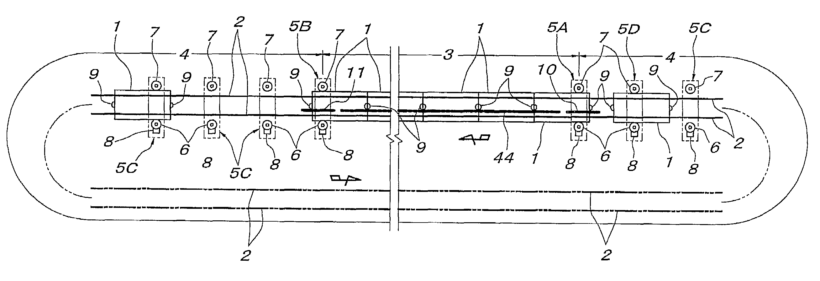
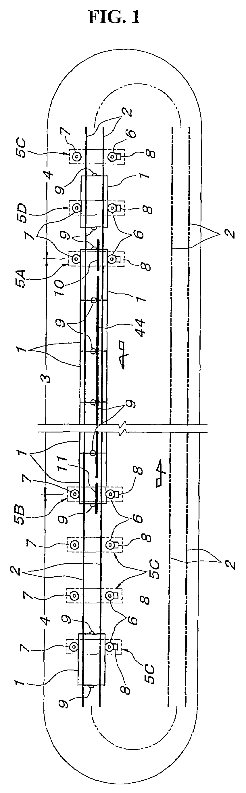
[0061]Hereinafter, a detailed embodiment of the invention will be described based on the accompanying drawings. In FIG. 1, the reference numerals 1 denote conveying carriers which travel on a cyclic traveling route including a pair of left and right guide rails 2. This cyclic traveling route is formed by connecting a rear-pushing traveling district 3 and a high-speed traveling district 4 which are straight and parallel to each other by U-turn paths, and in the drawings, only inlet and outlet regions of the rear-pushing traveling district 3 are shown and the remaining route is omitted. In the rear-pushing traveling district 3, a rear-pushing drive means 5A which propels the conveying carriers 1 at a constant speed is provided at an inlet of the rear-pushing traveling district, and a speed control drive means 5B for sending out the conveying carriers 1 at a constant speed is provided at an outlet. In the high-speed traveling district 4, high-speed drive means 5C which propel the conve...


PUM


Abstract

A carrier type conveying apparatus capable of solving a problem in a conventional conveying apparatus wherein a conveying carriers (1) stop abnormally, comprising a rear-pushing traveling district (3) having, at its inlet, a rear-pushing drive means (5A) propelling the conveying carriers (1) at a constant speed and, at its outlet, a speed control drive means (5B) for sending out the conveying carriers (1) at the constant speed and a high-speed traveling district (4). The conveying apparatus comprises carrier connection systems (carrier connection means (9), connection engagement means (10), connection release means (11)). When the conveying carriers (1) travel in the high-speed traveling district (4), the connection of the conveying carriers (1) adjacent to each other in the longitudinal direction by the carrier connection systems is disabled. Only when the conveying carriers (1) travel in the rear-pushing traveling district (3), the conveying carriers (1) in the longitudinal direction are connected to each other by the carrier connection system to prevent the conveying carriers (1) in contact with each other at their end parts from being separated a specified distance or longer from each other.

Description

TECHNICAL FIELD[0001]The present invention relates to a carrier type conveying apparatus including a rear-pushing traveling district for conveying carriers, to be used as a work line, and a high-speed traveling district to be used as a return line for returning the conveying carriers that have come out from the rear-pushing traveling district to an inlet of the rear-pushing traveling district, and a conveying carrier connection system of the carrier type conveying apparatus.BACKGROUND ART[0002]The rear-pushing traveling district of the carrier type conveying apparatus described above is provided with, at its inlet, a rear-pushing drive means for propelling the conveying carriers at a constant speed, and at its outlet, a speed control drive means for sending out the conveying carriers at a constant speed, and is known by, for example, Japanese Published Unexamined Patent Application No. Hei-05-170327. There is also known a constitution of a trolley type conveying traveling body in wh...

Claims


Application Information

Patent Timeline
IPC IPC(8): B65G35/06
CPCB61B13/127B65G35/06B61B13/12B61G1/02
Inventor HAYASHI, NOBUHIRO
Owner DAIFUKU CO LTD
Why Eureka
Try Eureka