Supercharge Your Innovation With Domain-Expert AI Agents!

Variable external interface circuitry on programmable logic device integrated circuits

a technology of integrated circuits and external interfaces, applied in logic circuit coupling/interface arrangements, instruments, pulse techniques, etc., can solve problems such as limited rang

Inactive Publication Date: 2010-02-09
ALTERA CORP
View PDF10 Cites 3 Cited by
  • Summary
  • Abstract
  • Description
  • Claims
  • Application Information

AI Technical Summary

Benefits of technology

The invention is about a programmable logic device (PLD) that can be used to create custom circuits. The device includes input signal nodes, input buffer circuitry, a circuit path, selectively usable AC coupling circuitry, a selectively usable resistance connection, and a selectively usable attenuation circuit. The device also has one or more sources of control signals that can be used to turn different parts of the circuit on or off, and adjust their resistance or attenuation. These controls can be programmed or dynamic. The PLD can be used in a variety of applications and can be designed to be single-ended or differential. The technical effects of this invention include the ability to create highly customizable circuits with programmable logic elements.

Problems solved by technology

This range may be limited due to concerns about oxide overstress or keeping transistors in the proper operating range.

Method used


Image

  • Variable external interface circuitry on programmable logic device integrated circuits
  • Variable external interface circuitry on programmable logic device integrated circuits
  • Variable external interface circuitry on programmable logic device integrated circuits

Examples


Embodiment Construction

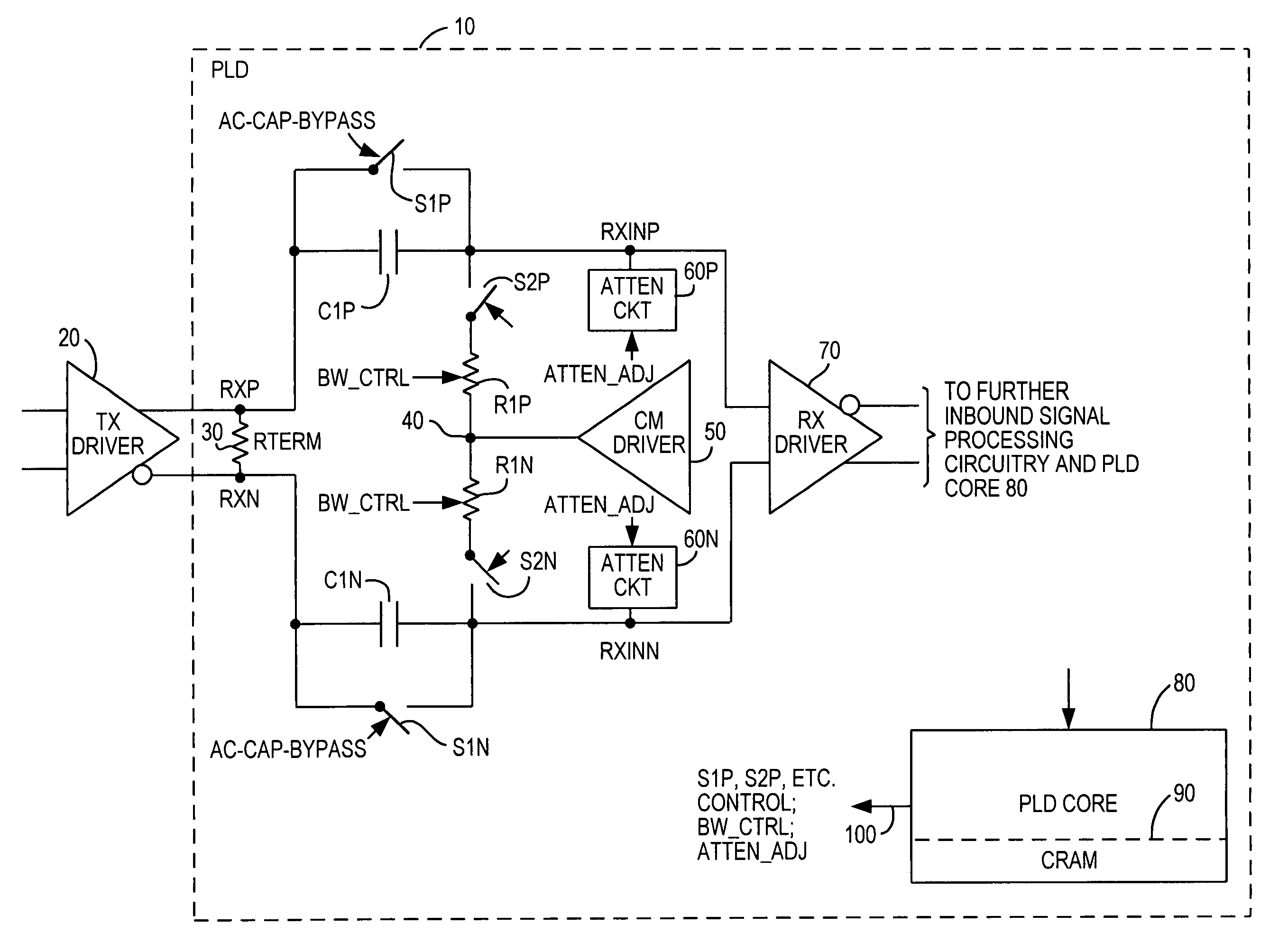
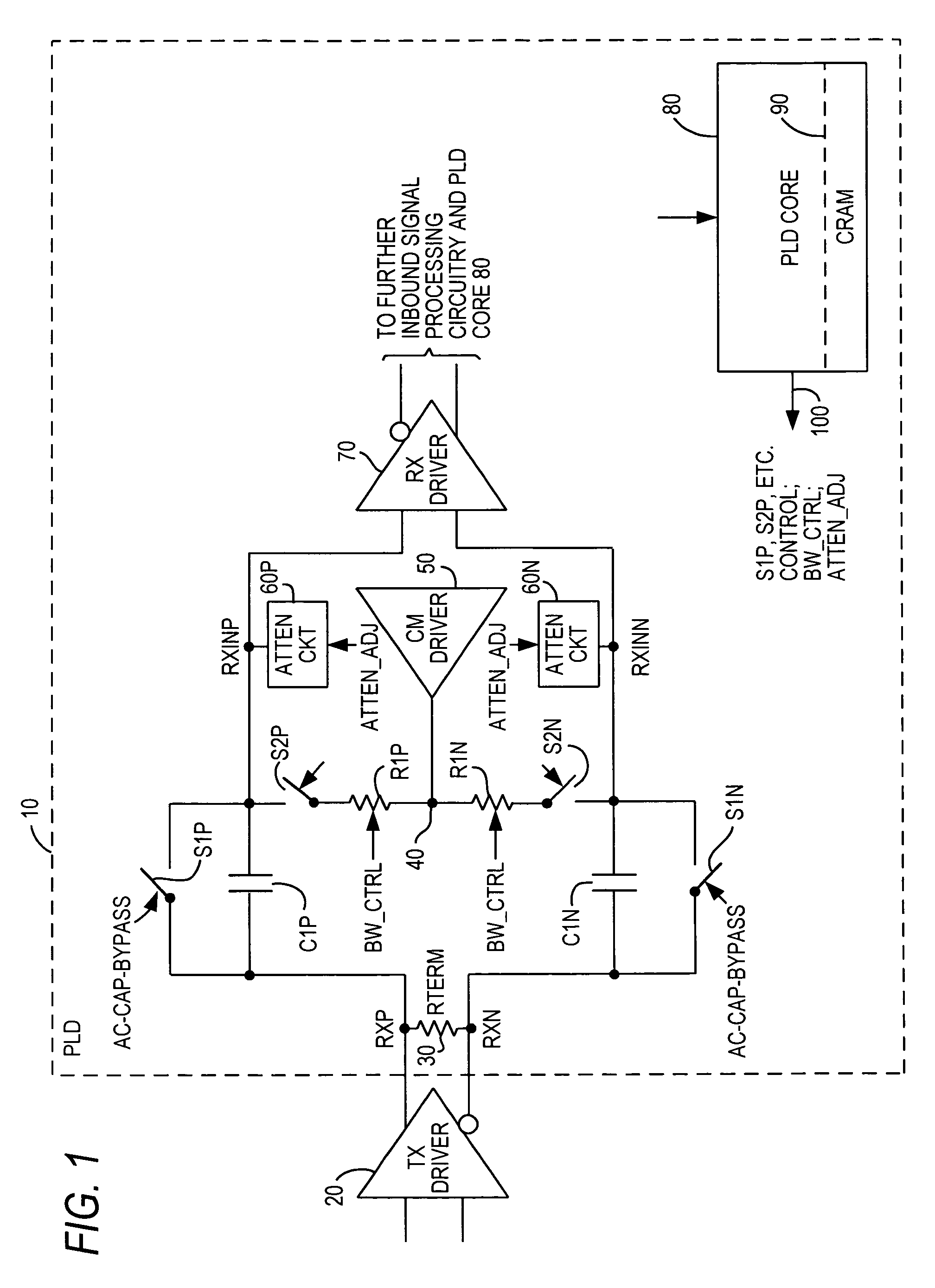
[0009]An illustrative embodiment of circuitry in accordance with the invention is shown in FIG. 1. This FIG. shows a PLD 10 in accordance with the invention receiving a signal from an external source (i.e., TX driver 20). In the particular example shown in FIG. 1, the signal from TX driver 20 is typically a high-speed serial data signal supplied in differential form, but the invention is equally applicable to single-ended implementations and to differential clock input implementations. The invention uses signals from elsewhere on PLD 10 (e.g., configuration random access memory (“CRAM”) or dynamic signals) to control the operation of the AC coupling capacitors, as well as the attenuation of the input signal to the PLD.

[0010]As shown in FIG. 1, the differential input signal to PLD 10 is connected across termination resistor 30. End node RXP of resistor 30 is connected to switch S1P and to AC coupling capacitor C1P. The other end node RXN of resistor 30 is connected to switch S1N and ...


PUM


Abstract

A programmable logic device (“PLD”) includes circuitry for optionally and variably modifying characteristics of an input signal in any of several respects. Examples of such modifications include AC coupling the signal into the PLD, low pass filtering the signal (with selectable low-pass filter corner frequency), shifting the common voltage of the input signal, and / or subjecting the input signal to a selectable amount of attenuation.

Description

[0001]This is a continuation of U.S. patent application Ser. No. 11 / 726,174, filed Mar. 20, 2007, now U.S. Pat. No. 7,417,462 which is hereby incorporated by reference herein in its entirety.BACKGROUND OF THE INVENTION[0002]This invention relates to programmable logic device integrated circuits (“PLDs”), and more particularly to circuitry on PLDs that is variable to facilitate connecting the PLD to various external signal sources.[0003]PLDs are typically intended to be relatively general-purpose devices. The market for a PLD product tends to be larger if the number of different applications in which that product can be successfully employed is greater. A PLD typically interacts with other devices in a system. The wider the range of different signals the PLD can successfully accept from such other system components, the greater the range of possible uses of the PLD, and therefore the greater the potential market for the PLD. By “different signals” in the preceding sentence, it is mea...

Claims


Application Information

Patent Timeline
Patent Type & Authority Patents(United States)
IPC IPC(8): H03K19/0175G06F7/38H03K5/00
CPCH03K19/17744
Inventor WONG, WILSONSHUMARAYEV, SERGEYTRAN, THUNGOC M.HOANG, TIM TRI
Owner ALTERA CORP
Features
  • R&D
  • Intellectual Property
  • Life Sciences
  • Materials
  • Tech Scout
  • Unparalleled Data Quality
  • Higher Quality Content
  • 60% Fewer Hallucinations
Learn More