Injection-locked frequency divider

a frequency divider and injection-locked technology, applied in the field can solve the problems of reducing system operation efficiency, bringing huge economic benefits, and improving human life quality, and achieve the effect of reducing phase noise and extending the lock range of injection-locked frequency dividers

Inactive Publication Date: 2010-02-09
NAT TAIWAN UNIV OF SCI & TECH
View PDF15 Cites 11 Cited by
  • Summary
  • Abstract
  • Description
  • Claims
  • Application Information

AI Technical Summary

Benefits of technology

[0010]Accordingly, the present invention is directed to an injection-locked frequency divider, which employs a voltage control oscillator (VCO) to generate an oscillation signal, and a mixer mixing the oscillation signal with an injection signal, so as to adjust and lock a frequency of the oscillation signal. The injection-locked frequency divider has advantages such as a wide locking range, and a low phase noise.
[0016]The injection-locked frequency divider according to the present invention feedbacks a oscillation signal generated by a VCO to an RF input terminal of a mixer, so as to mix the oscillation signal with an injection signal of a local input terminal of the mixer, and thus adjusting and locking the output frequency of the oscillation signal. In such a way, the locking range of the injection-locked frequency divider can be enlarged, and the phase noise thereof can be decreased accordingly.

Problems solved by technology

The rapid development of wireless communication, not only drastically improves quality of human life, but also brings huge economic profit.
Typically, a frequency divider often consumes much power when operating under a high frequency, so as to decrease the operation efficiency of the system.
However, when the oscillation frequency fo is too much different from a half of the injection signal (fi / 2), the injection-locked frequency divider 100 is then incapable of locking the frequency of the frequency dividing signal S1.
Although the conventional injection-locked frequency divider 100 is adapted for operation under a very high frequency, unfortunately its locking range is too narrow, so that the injection-locked frequency divider 100 has too narrow a range for frequency dividing.
Even though the variable capacitors Cf1, Cf2 are employed for adjusting the oscillation frequency, the locking range can not be effectively improved.

Method used


Image

  • Injection-locked frequency divider
  • Injection-locked frequency divider
  • Injection-locked frequency divider

Examples


Embodiment Construction

[0024]Reference will now be made in detail to the present preferred embodiments of the invention, examples of which are illustrated in the accompanying drawings. Wherever possible, the same reference numbers are used in the drawings and the description to refer to the same or similar parts.

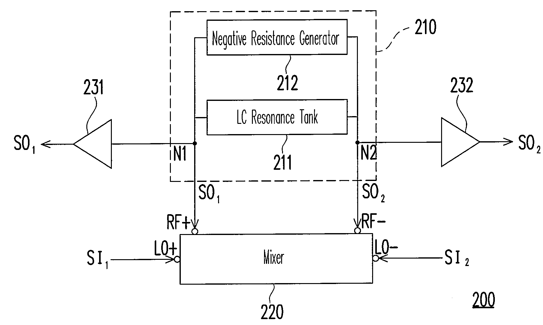
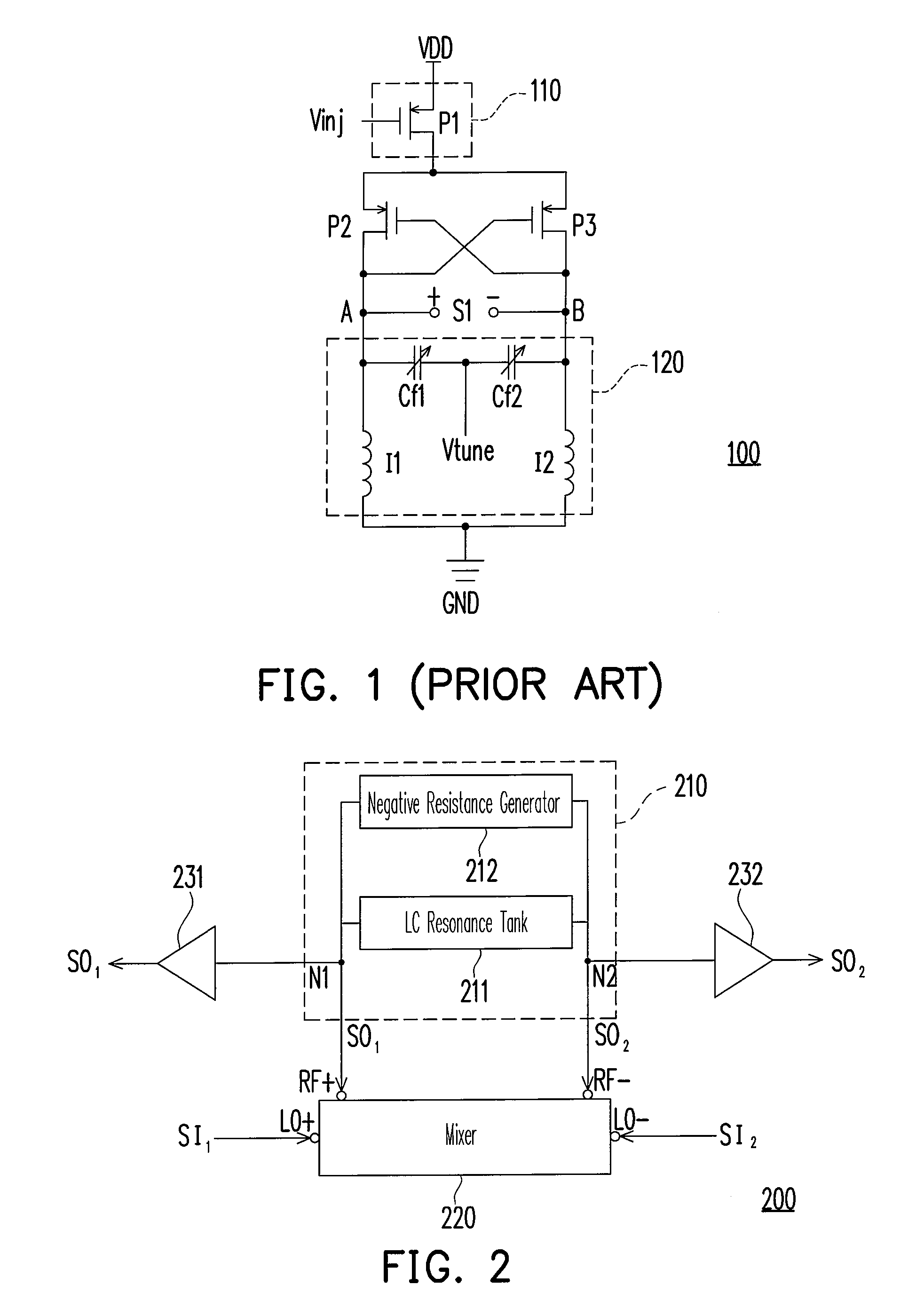
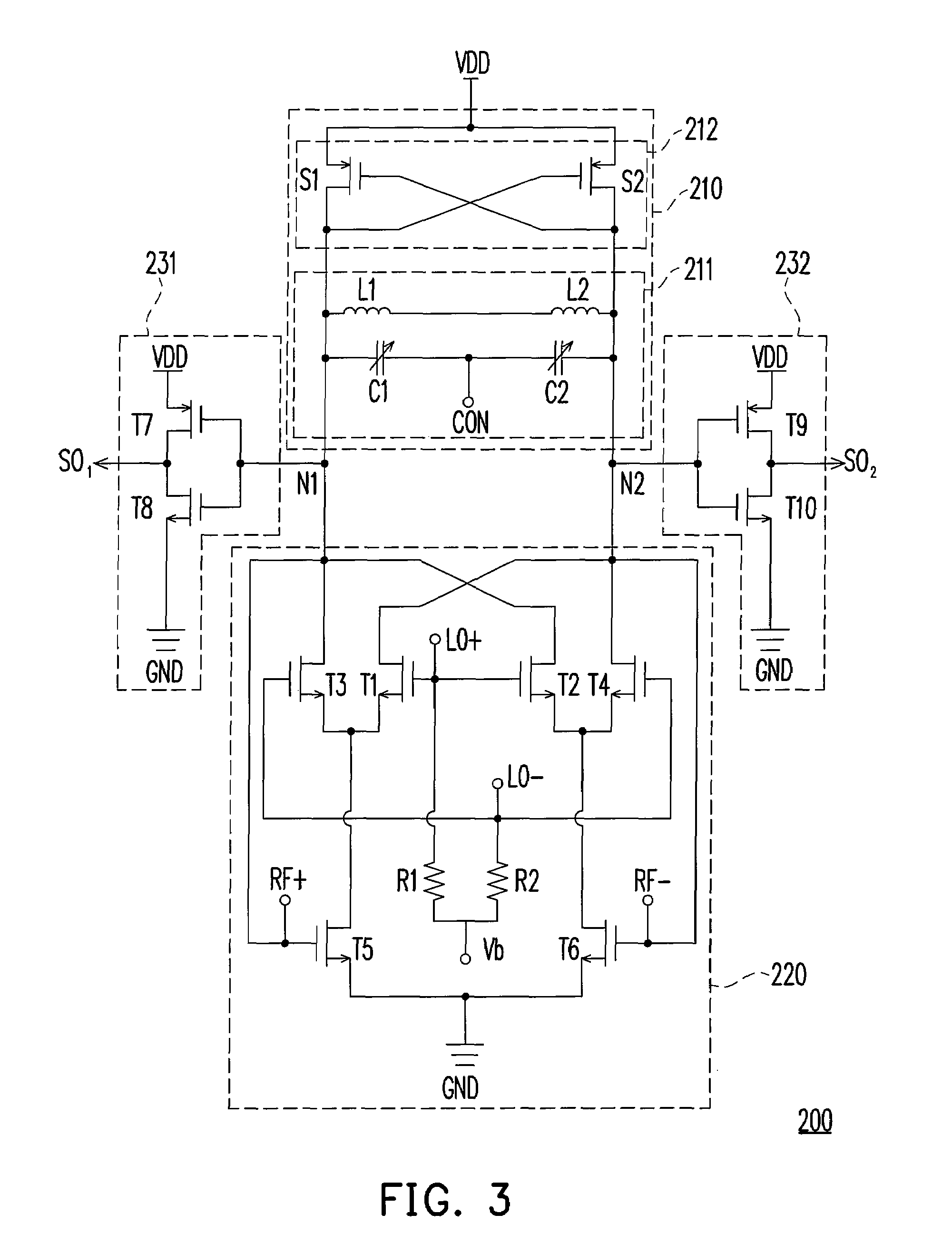
[0025]FIG. 2 illustrates a structural diagram of an injection-locked frequency divider according to an embodiment of the present invention. Referring to FIG. 2, there is shown an injection-locked frequency divider 200 including a voltage control oscillator (VCO) 210, a mixer 220, and buffers 231 and 232. The VCO 210 includes an LC resonance tank 211, and a negative resistance generator 212. The VCO 210 generates a differential oscillation signal SO via a resonance of the LC resonance tank 211. The differential oscillation signal SO includes a first oscillation signal SO1, and a second oscillation signal SO2. The first oscillation signal SO1 and the second oscillation signal SO2 are respectively ou...


PUM


Abstract

An injection-locked frequency divider is provided. The injection-locked frequency divider includes a voltage control oscillator (VCO) and a mixer. The VCO includes a LC resonance tank and a negative-resistance generator for generating a differential oscillation signal including a first and a second oscillation signals. The LC resonance tank adjusts a VCO reactance and resonates for generating the differential oscillation signal. The negative-resistance generator coupled to the LC resonance tank eliminates an equivalent resistance generated by the LC resonance tank and maintains the VCO to continuously oscillate. The mixer has a first and a second local input terminals respectively receiving the first and second injected signals included in a differential injected signal, and the first and second radio frequency input terminals respectively receiving the first and second oscillation signals for mixing the differential injected signal with the differential oscillation signal to adjust the output frequency of the differential oscillation signal.

Description

CROSS-REFERENCE TO RELATED APPLICATION[0001]This application claims the priority benefit of Taiwan application serial no. 96138997, filed on Oct. 18, 2007. The entirety of the above-mentioned patent application is hereby incorporated by reference herein and made a part of this specification.BACKGROUND OF THE INVENTION[0002]1. Field of the Invention[0003]The present invention generally relates to an injection-locked frequency divider, and more particularly, to an injection-locked frequency divider, based on a mixer and a voltage control oscillator, having a wide injection-locking range and a low phase noise.[0004]2. Description of Related Art[0005]The rapid development of wireless communication, not only drastically improves quality of human life, but also brings huge economic profit. Up to now, one may instantly communicate and share information with others simply by a notebook, a personal digital assistant, or a cellular phone. In a typical wireless communication system, a frequenc...

Claims


Application Information

Patent Timeline
Patent Type & Authority Patents(United States)
IPC IPC(8): H03B21/00
CPCH03B19/14H03B5/1221H03B5/1228H03B5/1215H03B5/1243H03B5/1209H03B2200/0074H03D7/14
Inventor JANG, SHENG-LYANGLIU, CHENG-CHEN
Owner NAT TAIWAN UNIV OF SCI & TECH
Why Eureka
Try Eureka