Flexible carry scheme for field programmable gate arrays

Inactive Publication Date: 2010-02-16
MICROSEMI SOC
View PDF16 Cites 24 Cited by
  • Summary
  • Abstract
  • Description
  • Claims
  • Application Information

AI Technical Summary

Problems solved by technology

Volatile control elements, such as SRAM bits, lose their programming data when the PLD power supply is disconnected, disabled or turned off.
The ripple carry adder of FIG. 2C is often the least expensive in terms of silicon area to implement in hardware, but it has the disadvantage of being slow when wide numbers with lots of bits are being added because the speed limiter is the time it takes for the carry signal to propagate from the least significant bit to the most significant bit.
The cost of this approach is an adder that takes roughly twice the area to implement since twice as many adder bits are required.
Thus for very wide

Method used


Image

  • Flexible carry scheme for field programmable gate arrays
  • Flexible carry scheme for field programmable gate arrays
  • Flexible carry scheme for field programmable gate arrays

Examples


Embodiment Construction

[0041]Those of ordinary skill in the art will realize that the following description of the present invention is illustrative only and not in any way limiting. Other embodiments of the invention will readily suggest themselves to such skilled persons.

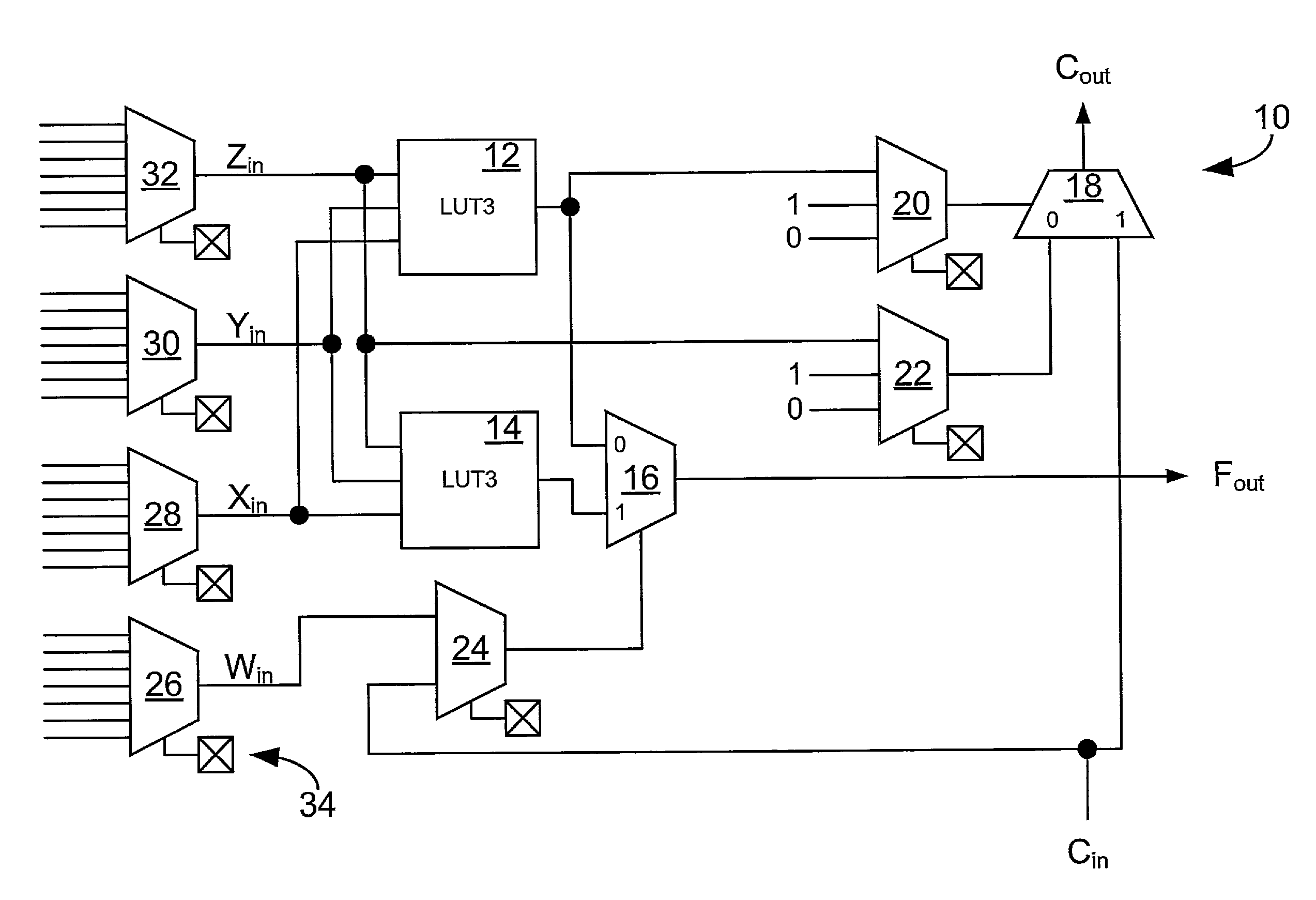
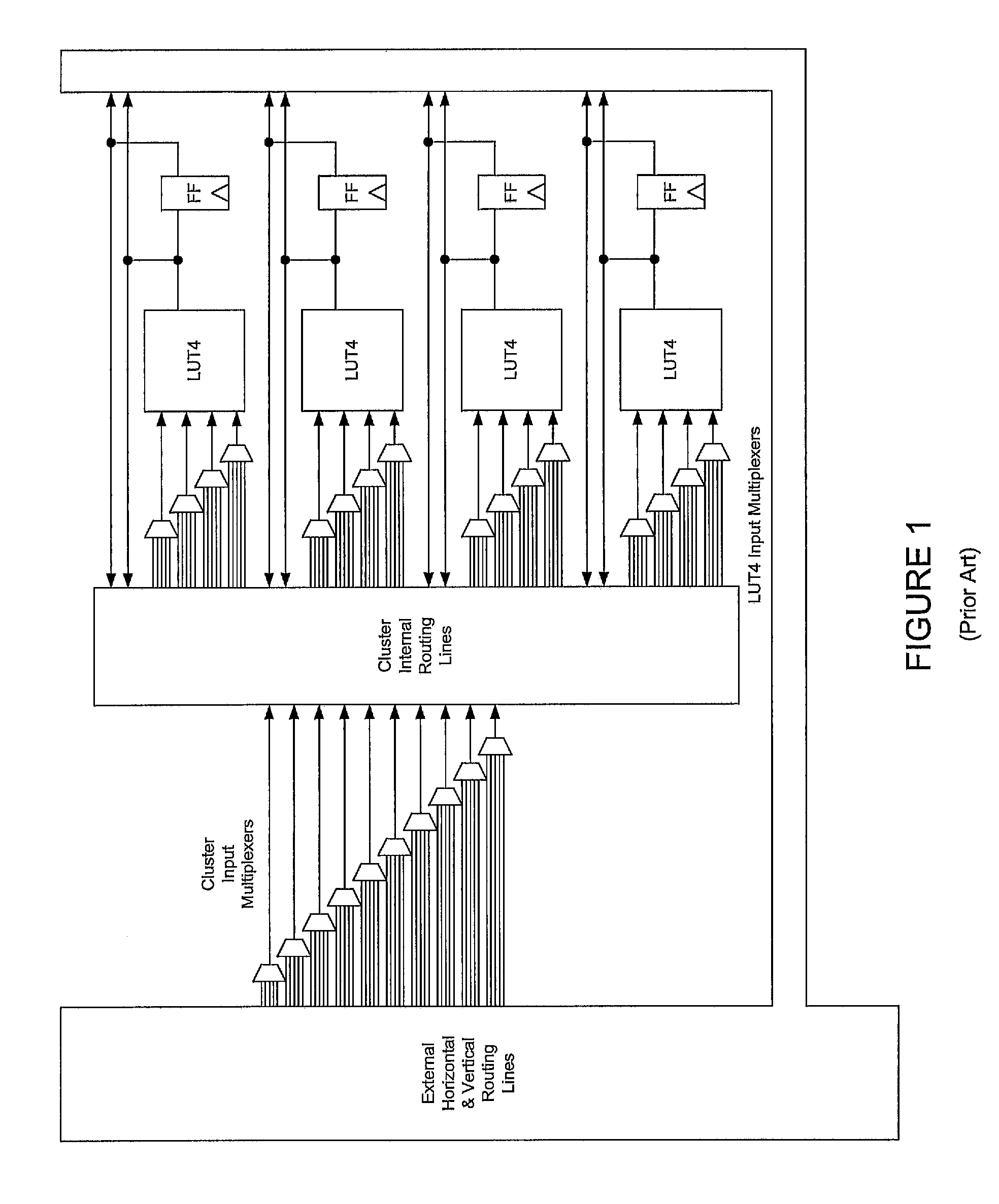
[0042]Turning to FIG. 6A a logic module indicated generally by reference number 10 is shown. Logic module 10 comprises a logic function generator circuit and a carry circuit coupled to one another. The function generator circuit comprises LUT3 block 12, LUT3 block 14, multiplexer 16, input nodes Win, Xin, Yin, Zin, and output node Fout. The carry circuit comprises multiplexers 18, 20 and 22, input node Cin, and output node Cout. The function generator and the carry circuit share multiplexer 24. Also shown in FIG. 6A are LUT4 input multiplexers 26, 28, 30, and 32 which are analogous to the LUT4 input multiplexers shown in FIG. 1. The function generator circuit is capable of generating any logic function of four binary variables (like the...


PUM


Abstract

A fast, flexible carry scheme for use in clustered field programmable gate array architectures is described. Each cluster has a cluster carry input node, a cluster carry output node, a cluster carry output circuit having an output coupled to the cluster carry output node, a first input coupled to the cluster carry input node, and a second input and a plurality of logic modules each comprising a logic function generator circuit coupled to a carry circuit. The logic modules are coupled in a series carry arrangement between the cluster carry input node and the second input of the cluster carry output circuit such that the least significant bit of an arithmetic logic circuit can be programmably placed in any of the logic modules.

Description

BACKGROUND OF THE INVENTION[0001]1. Field of the Invention[0002]The invention pertains to the field of integrated circuits. More particularly, the invention pertains to field programmable gate array integrated circuit devices.[0003]2. Description of Related Art[0004]Field Programmable Gate Array (FPGA) integrated circuit devices are known in the art. An FPGA comprises any number of initially uncommitted logic modules arranged in an array along with an appropriate amount of initially uncommitted routing resources. Logic modules are circuits which can be configured to perform a variety of logic functions like, for example, AND-gates, OR-gates, NAND-gates, NOR-gates, XOR-gates, XNOR-gates, inverters, multiplexers, adders, latches, and flip / flops. Routing resources can include a mix of components such as wires, switches, multiplexers, and buffers. Logic modules, routing resources, and other features like, for example, I / O buffers and memory blocks, are the programmable elements of the F...

Claims


Application Information

Patent Timeline
IPC IPC(8): H03K19/173G06F7/42G06F15/00
CPCG06F7/506H03K19/17728
Inventor PLANTS, WILLIAM C.
Owner MICROSEMI SOC
Why Eureka
Try Eureka