Steering gear assembly having rack bushing

a technology of steering gear and bushing, which is applied in the direction of elastic bearings, bearing units, rigid supports, etc., can solve the problems of limiting radial expansion and contraction, affecting the performance of the steering gear, and prone to hoop encountering, etc., and achieves the effect of convenient installation and low manufacturing cos

Inactive Publication Date: 2010-02-23
STEERING SOLUTIONS IP HLDG +1
View PDF33 Cites 50 Cited by
  • Summary
  • Abstract
  • Description
  • Claims
  • Application Information

AI Technical Summary

Benefits of technology

[0008]The present invention provides a rack and pinion steering gear assembly having a well-performing bushing that can be inexpensively manufactured and easily installed.

Problems solved by technology

Such a bushing, however, does still tend to encounter hoop stresses which limit such radial expansions and contractions.
Clearances between the bushing and rack or between the bushing and housing, however, can, in certain driving conditions, create objectionable rattle noise that can be heard by the driver and passengers.
Such objectionable noise tends to grow louder as the bushing wears and the clearances increase and is the source of significant warranty issues.
Those steering gears having a high inertia above the steering gear often suffer from such objectionable noises and non-assisted standard manual rack and pinion gears and column assist and single pinion assist electric power steering systems are particularly susceptible to such objectionable noises.
Hydraulic gears are not as susceptible to such rattle noises as manual gears, but the concern with such objectionable noises may still be present in such applications.

Method used


Image

  • Steering gear assembly having rack bushing
  • Steering gear assembly having rack bushing
  • Steering gear assembly having rack bushing

Examples


embodiment 20

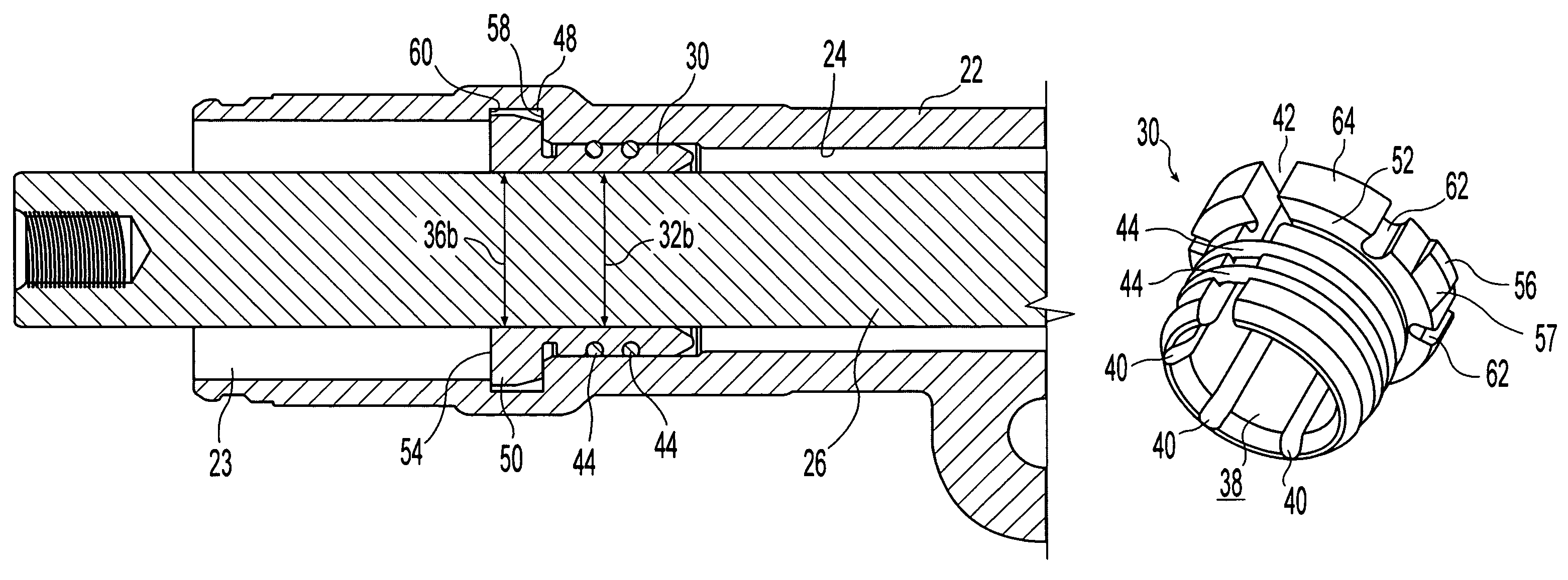
[0049]It is further noted that while the illustrated embodiment utilizes two O-rings 44, alternative embodiments could employ a single O-ring or other single suitable compressible member to provide a delashing function. One consequence of utilizing a single O-ring 44 is that it provides a single line of contact with housing 22. This could, potentially, lead to the bushing tilting back and forth about this single line of contact between two different positions in a manner not unlike that of a teeter-totter. If such tilting action were to occur, the repositioning of the bushing each time it tilted between positions would cause an undesirable noise. The use of two spaced apart O-rings 44, as exemplified in the illustrated embodiment 20, provides two spaced apart lines of contact with interior bore 24 of housing 22 and thereby inhibits the tilting movement of bushing 30.

embodiment 30

[0050]It is also noted that although the disclosed embodiment 30 has been described as an acetal bushing, other suitable materials may alternatively be employed to manufacture bushing 30. Furthermore, while the illustrated bushing 30 does not include a Teflon coating, alternative embodiments of bushing 30 could take the form of an injection molded acetal material with a Teflon coating.


PUM

PropertyMeasurementUnit
axial thicknessaaaaaaaaaa
diameteraaaaaaaaaa

Abstract

A rack and pinion steering gear assembly including a housing, a rack that is translatably moveable relative to the housing along an axis and a bushing operably disposed between the rack and housing. The bushing defines a gap which extends the entire axial length of the bushing. At least one compressible member may be disposed between the bushing and the housing with the compressible member extending across the gap in the bushing and fully encircling the bushing. The bushing may also include a radial flange that acts as a travel stop. The bushing may also be formed of an acetal material wherein the flange and a tubular portion of the bushing are axially separated by an intermediate portion having a relatively thin radial thickness. Axially extending recesses may be provided to enhance the flexibility of the bushing.

Description

CROSS REFERENCE TO RELATED APPLICATIONS[0001]This application claims priority under 35 U.S.C. 119(e) of U.S. provisional patent application Ser. No. 60 / 851,414 filed on Oct. 13, 2006 entitled RACK AND PINION STEERING GEAR ASSEMBLY HAVING C-SHAPED RACK BUSHING the disclosure of which is hereby incorporated herein by reference.BACKGROUND OF THE INVENTION[0002]1. Field of the Invention[0003]The present invention relates to steering gear assemblies and, more particularly, to rack and pinion steering gear assemblies having at least one rack bushing.[0004]2. Description of the Related Art[0005]Conventional rack and pinion steering gear assemblies, whether manual or having an electric or hydraulic power assist, typically include a bushing that provides a low friction-sliding surface for rack translation along a Y-axis and rotation about its centerline while supporting the rack in the X and Z directions in a mutually perpendicular X-Y-Z coordinate system. Rack bushings are typically install...

Claims


Application Information

Patent Timeline
Patent Type & Authority Patents(United States)
IPC IPC(8): B62D3/12F16C27/06
CPCB62D3/12F16C29/02F16C29/002F16C33/20F16C2240/40F16C2208/66
Inventor ARLT, GEORGE E.
Owner STEERING SOLUTIONS IP HLDG
Why Eureka
Try Eureka