Vortex cooled turbine blade outer air seal for a turbine engine

a technology of outer air seal and turbine blade, which is applied in the direction of machines/engines, liquid fuel engines, mechanical equipment, etc., to achieve the effect of reducing the operating temperature of the outer air seal of the turbine blade, reducing the requirement of cooling fluid flow, and increasing the convection rated

Inactive Publication Date: 2010-02-23
SIEMENS ENERGY INC
View PDF36 Cites 16 Cited by
  • Summary
  • Abstract
  • Description
  • Claims
  • Application Information

AI Technical Summary

Benefits of technology

[0008]An advantage of this invention is that the vortex cooling channels in the turbine blade outer air seal increase the convection rated in the cooling system by creating vortices of the cooling fluids.
[0009]Another advantage of this invention is that the vortexed cooling fluids reduce the cooling fluid flow requirement and reduce the operating temperature of the turbine blade outer air seal.
[0010]Yet another advantage of this invention is that the channel feed holes may be positioned along the length of the vortex cooling channels to resupply the vortex cooling channels with fresh cooling fluids to continue the vortex and to reduce the temperature of the cooling fluids in the vortex cooling channels.
[0011]Another advantage of this invention is that the cooling fluid delivered to each vortex channel may be independently controlled by varying the size of the vortex channel feed holes so that each vortex channel may be configured for the local heat load and in addition, a local over temperature may be accounted for by increasing the size of the appropriate vortex channel feed holes to supply additional cooling fluids to the area. Thus, the temperature of each vortex channel may be individually tuned.

Problems solved by technology

Conventional cooling systems in the outer air seals often require large cooling fluid supply flows.

Method used


Image

  • Vortex cooled turbine blade outer air seal for a turbine engine
  • Vortex cooled turbine blade outer air seal for a turbine engine
  • Vortex cooled turbine blade outer air seal for a turbine engine

Examples


Embodiment Construction

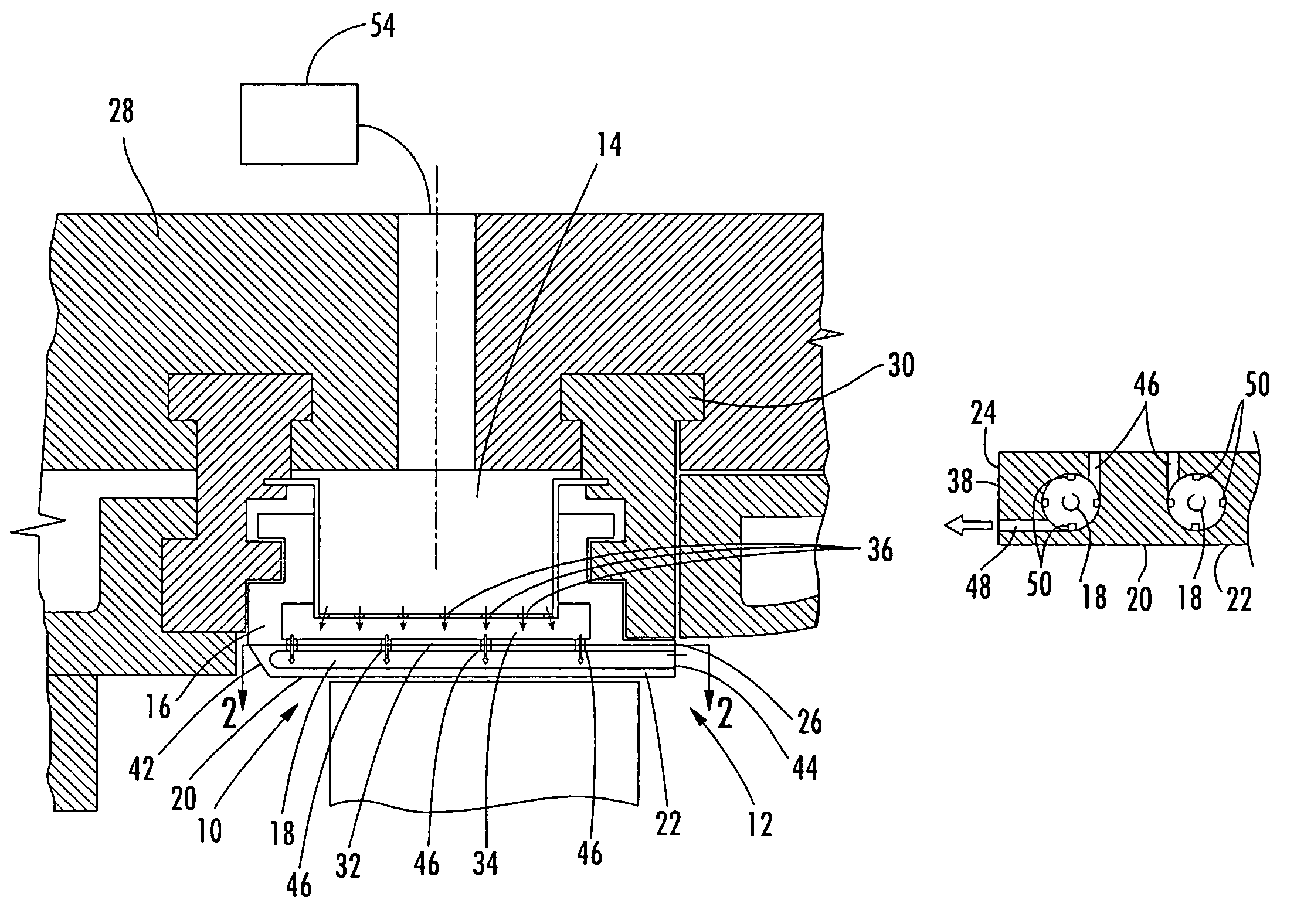
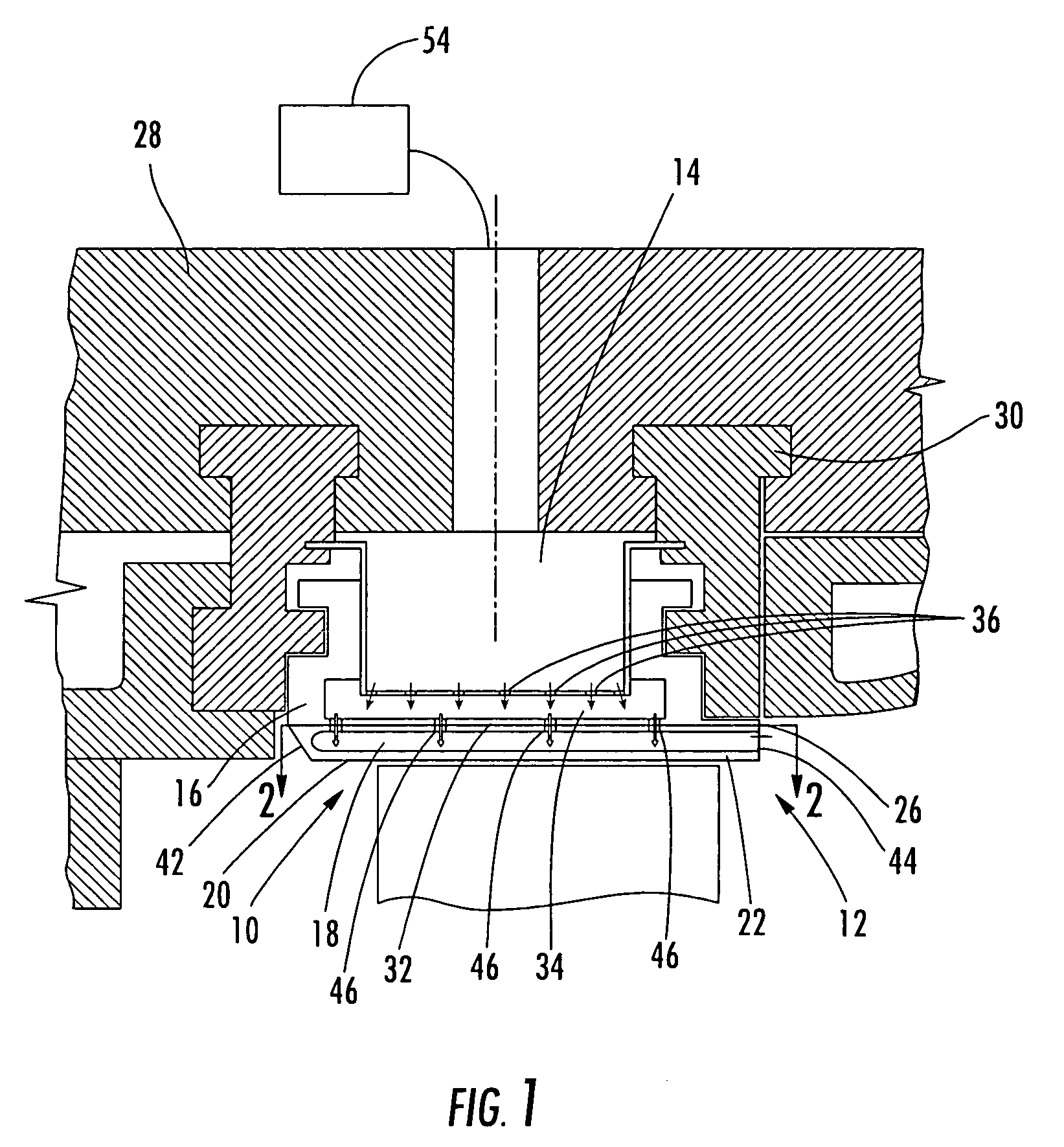
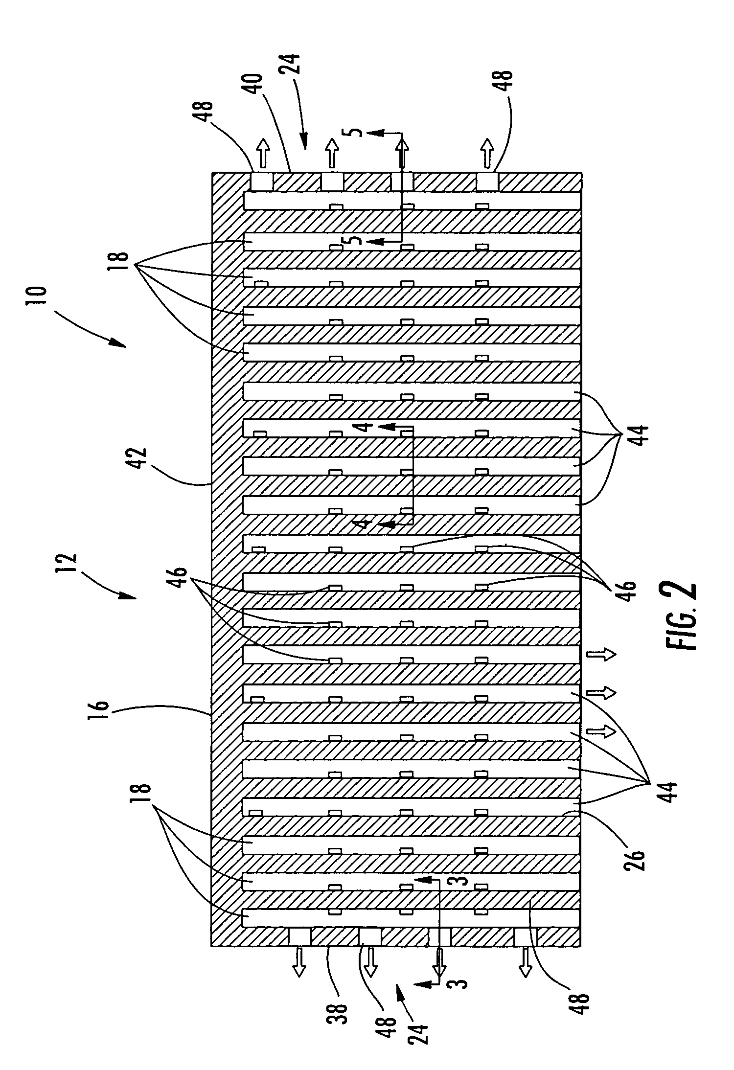
[0019]As shown in FIGS. 1-5, this invention is directed to a turbine blade outer air seal cooling system 10 for a turbine blade outer air seal 12 used in turbine engines. In particular, the turbine blade outer air seal cooling system 10 may include one or more cooling fluid collection chambers 14 positioned with an outer seal housing 16 and in fluid communication with one or more vortex cooling channels 18 in the outer seal housing 16. The vortex cooling channels 18 may be positioned in close proximity to an outer sealing surface 20 on an outer plate 22 of the outer seal housing 16. The vortex cooling channels 18 may be in fluid communication with the cooling fluid collection chamber 14 to receive cooling fluids to create one or more vortices in the vortex cooling channels 18. The cooling fluids may flow through the vortex cooling channels 18 in a general vortex motion and be expelled on side surfaces 24 and a downstream edge 26 of the outer plate 22.

[0020]The turbine blade outer ai...


PUM


Abstract

A cooling system for a turbine blade outer air seal that is positioned in close proximity to a tip of a rotatable turbine airfoil to seal the gap between the tip of the turbine blade and the blade ring carrier. The turbine blade outer air seal may be formed from a housing including a cooling fluid collection chamber and one or more vortex cooling channels in fluid communication with the cooling fluid collection chamber via one or more vortex channel feed holes. In one embodiment, a plurality of vortex cooling channels may extend from proximate to an upstream edge of an outer sealing plate of the outer air seal to a downstream edge of the outer sealing plate. During use, cooling fluids pass through the vortex channel feed holes and into the vortex cooling channels, in which vortices may be created.

Description

FIELD OF THE INVENTION[0001]This invention is directed generally to turbine airfoils, and more particularly to cooling systems in outer air seals proximate to turbine blades in turbine engines.BACKGROUND[0002]Typically, gas turbine engines include a compressor for compressing air, a combustor for mixing the compressed air with fuel and igniting the mixture, and a turbine blade assembly for producing power. Combustors often operate at high temperatures that may exceed 2,500 degrees Fahrenheit. Typical turbine combustor configurations expose turbine blade assemblies to these high temperatures. As a result, turbine blades must be made of materials capable of withstanding such high temperatures. Turbine blades and other components often contain cooling systems for prolonging the life of the blades and reducing the likelihood of failure as a result of excessive temperatures.[0003]Turbine blades typically extend radially from a rotor assembly and terminate at a tip within close proximity ...

Claims


Application Information

Patent Timeline
Patent Type & Authority Patents(United States)
IPC IPC(8): F01D25/12F01D11/08
CPCF01D11/24F05D2240/11F05D2260/201F05D2260/205
Inventor LIANG, GEORGE
Owner SIEMENS ENERGY INC
Why Eureka
Try Eureka