Stator structure and manufacturing method thereof

a technology of stator and manufacturing method, which is applied in the direction of machine/engine, positive displacement liquid engine, piston pump, etc., can solve the problems of reducing the lifetime of the motor, affecting the efficiency of the motor, and affecting the performance of the motor, so as to achieve the effect of isolation from the environmen

Active Publication Date: 2010-02-23
DELTA ELECTRONICS INC
View PDF14 Cites 51 Cited by
  • Summary
  • Abstract
  • Description
  • Claims
  • Application Information

AI Technical Summary

Benefits of technology

[0009]To achieve the above, a manufacturing method of a stator structure according to the present invention includes the steps of providing at least one first cover having an accommodation space; disposing a stator assembly in the accommodation space of the first cover, and applying a filler between the first cover and the stator assembly. The stator assembly is surrounded by the first cover and the filler such that the stator assembly is isolated from the environment. Accordingly, the product including the stator structure is capable of being applied to wet or high-salted environment, to achieve the effect of water-proofing and enhance its performance.
[0011]To achieve the above, another manufacturing method of a stator structure according to the present invention includes the steps of disposing a stator assembly on a base of a fan frame; providing at least one first cover having an accommodation space; connecting the first cover with the fan frame to make the stator assembly located between the first cover and the base; and applying a filler between the first cover and the base of the fan frame. The stator assembly is effectively isolated from the environment by the method. A product including such stator structure is capable of being applied to wet or high-salted environment, to achieve the effect of water-proofing.

Problems solved by technology

However, the stator structure, including a coil and a circuit board, of the motor is sensitive to moisture which will cause the interior of the motor to be moist and lower the lifetime of the motor.
However, this kind of protection is still limited and is not enough.

Method used


Image

  • Stator structure and manufacturing method thereof
  • Stator structure and manufacturing method thereof
  • Stator structure and manufacturing method thereof

Examples


first embodiment

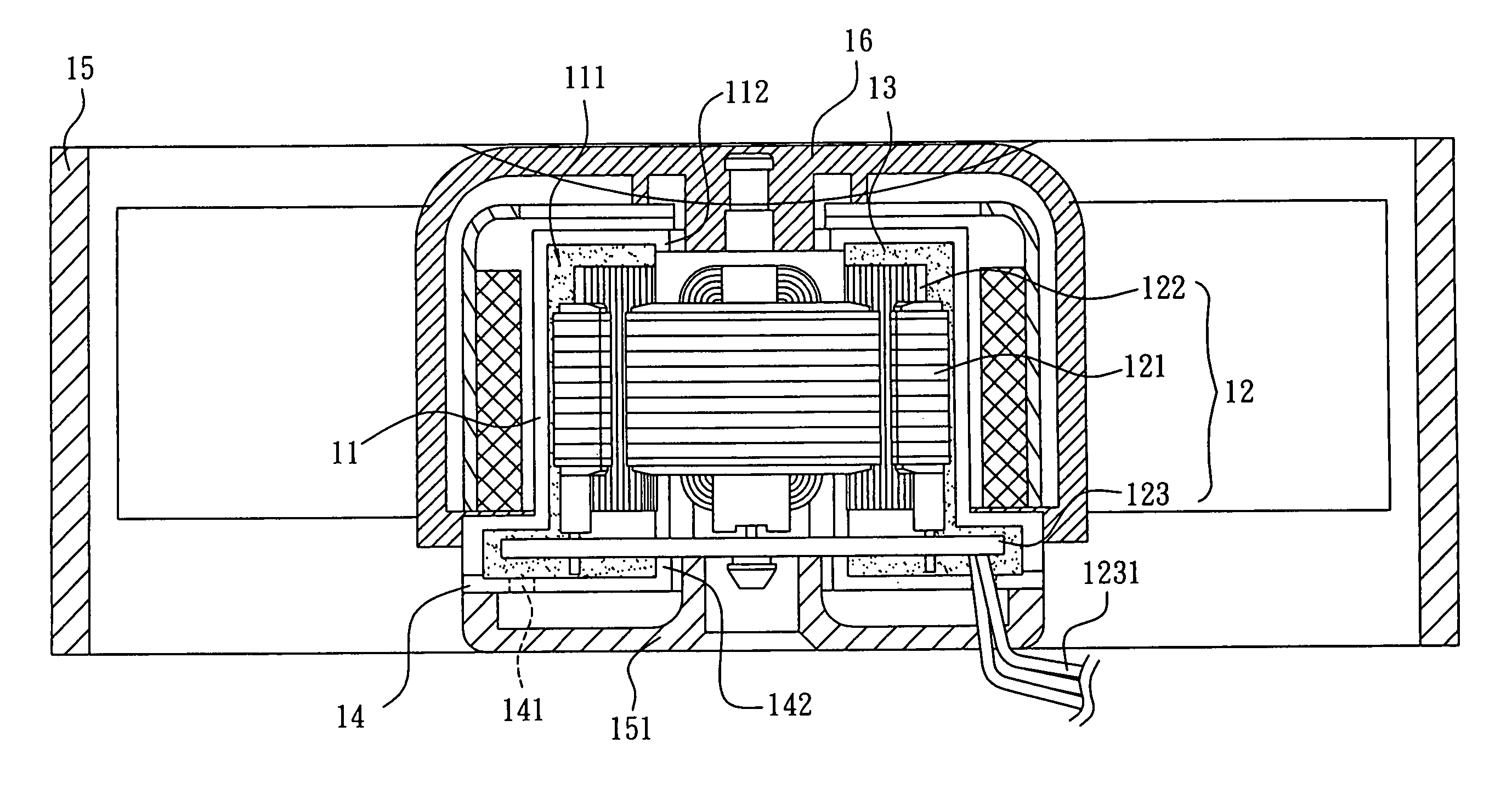
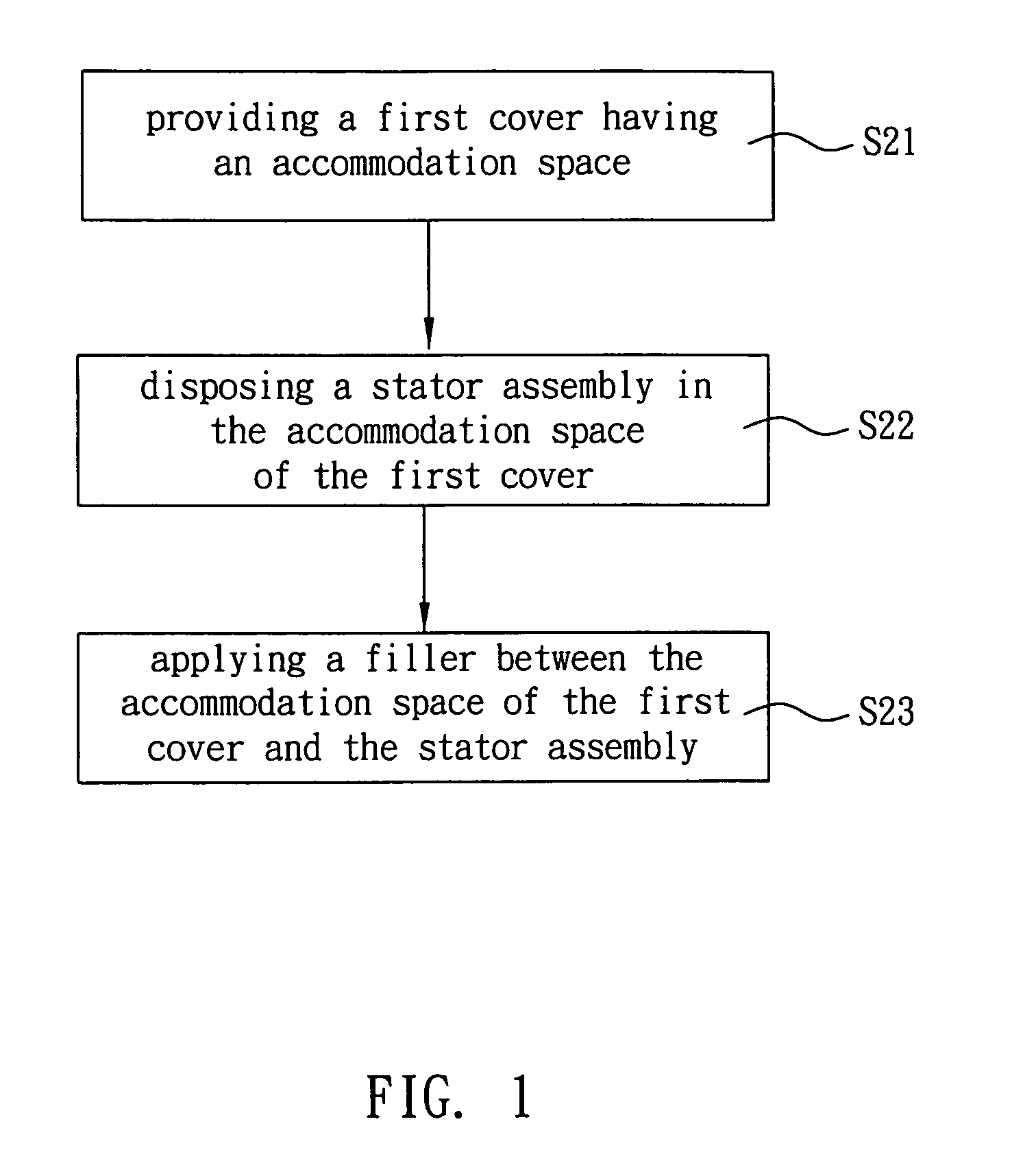
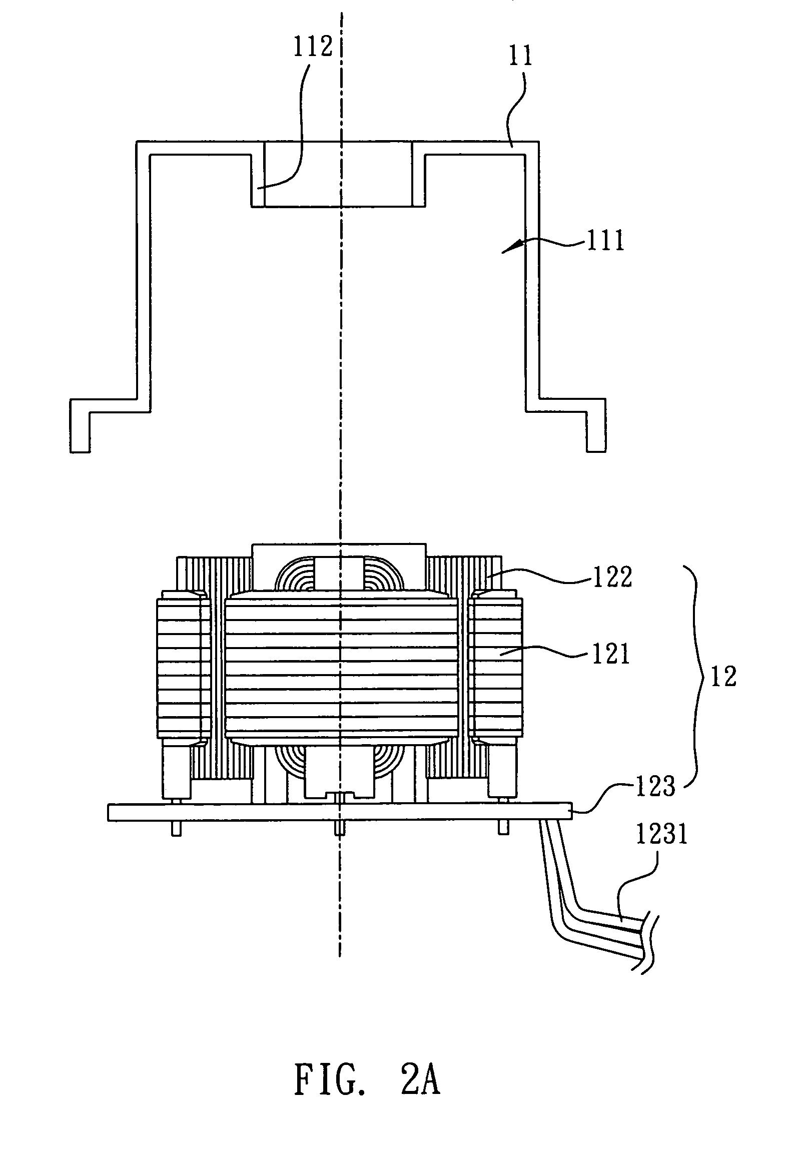
[0021]FIGS. 1 to 2D show a manufacturing method of a stator structure according to the present invention. The manufacturing method of this embodiment includes the steps S21 to S23. As shown in FIGS. 1 and 2A, step S21 is to provide a first cover 11 having an accommodation space 111. The first cover 11 of this embodiment has a restricting portion 112. The material of the first cover 11 includes but not limited to plastics, acryl or metal.

[0022]As shown in FIGS. 1 and 2B, step S22 is to dispose a stator assembly 12 in the accommodation space 111 of the first cover 11. In this embodiment, the stator assembly 12 is in contact with the restricting portion 112. The stator assembly 12 includes a plurality of stacked silicon steel sheets 121, a coil 122 winding on the silicon steel sheets 121, and a circuit board 123 located at one side of the silicon steel sheets 121 and electrically connected with the silicon steel sheets 121. A wire 1231 is electrically connected with the circuit board 1...

second embodiment

[0027]FIGS. 4 to 5C show a manufacturing method of a stator structure according to the present invention. The manufacturing method of this embodiment includes the steps S01 to S04. As shown in FIGS. 4 and 5A, step S01 is to provide a first cover 11, a stator assembly 12 and a second cover 14. The first cover 11 has an accommodation space 111 and a restricting portion 112. The second cover 14 also has a restricting portion 142. The first cover 11 and the second cover 14 are made of plastics, acryl or metal.

[0028]As shown in FIGS. 4 and 5B, step S02 is to dispose the stator assembly 12 between the accommodation space 111 of the first cover 11 and the second cover 14. In this embodiment, the stator assembly 12 is in contact with the restricting portion 112 and the restricting portion 142 so as to be restricted. The stator assembly 12 includes a plurality of stacked silicon steel sheets 121, a coil 122 and a circuit board 123. The silicon steel sheets 121, the coil 122 and the circuit b...

third embodiment

[0033]FIGS. 6 to 7C show a manufacturing method of a stator structure according to the present invention. The manufacturing method of this embodiment includes the steps S11 to S14. As shown in FIGS. 6 and 7A, step S11 is to dispose a stator assembly 21 on a base 221 of a fan frame 22. The stator assembly 21, which is the same as that described in the previous embodiment, includes a plurality of stacked silicon steel sheets 211, a coil 212 and a circuit board 213.

[0034]As shown in FIGS. 6 and 7B, step S12 is to provide a first cover 23 having an accommodation space 231 for receiving the stator assembly 21. Step S13 is to connect the first cover 23 with the fan frame 22 to make the stator assembly 21 located between the first cover 23 and the base 221. The first cover 23 of this embodiment is made of, including but not limited to, plastics, acryl or metal. In addition, the first cover 23 and the fan frame 22 are connected, including but not limited, by engaging, lodging, locking or ad...


PUM


Abstract

A stator structure includes a first cover, a stator assembly and a filler. The first cover has an accommodation space for accommodating the stator assembly therein. The filler is applied between the first cover and the stator assembly to surround the stator assembly. A manufacturing method of the stator structure is also disclosed.

Description

BACKGROUND OF THE INVENTION[0001]1. Field of Invention[0002]The present invention relates to a stator structure and a manufacturing method thereof, and more particularly to a stator structure with water-proof effect and a manufacturing method thereof.[0003]2. Related Art[0004]Accompanying with the development of electronic industry, motor has been widely applied to lots of fields and has become one of the well-developed technologies in the industry. Vehicles, fans, water pumps, and even computer peripheral devices, for example printers or scanners, are all using motor to operate. However, the stator structure, including a coil and a circuit board, of the motor is sensitive to moisture which will cause the interior of the motor to be moist and lower the lifetime of the motor.[0005]Take the fan as an example, the traditional common method to protect the moisture entering the internal elements of the motor is to shorten the gaps between the rotor structure and the stator structure and ...

Claims


Application Information

Patent Timeline
Patent Type & Authority Patents(United States)
IPC IPC(8): H02K5/10H02K5/12
CPCH02K5/04H02K5/10H02K5/08H02K15/12H02K15/14
Inventor LEE, CHIEN-MINGFU, DENG-CHUCHEN, YING-CHIHUANG, WEN-SHI
Owner DELTA ELECTRONICS INC
Why Eureka
Try Eureka