
Single mode photonic circuit architecture and a new optical splitter design based on parallel waveguide mode conversion

a photonic circuit and waveguide mode technology, applied in the direction of optical waveguide light guide, instruments, optical elements, etc., can solve the problems of single mode operation condition of waveguide, inability to use devices in the system, and significant mode dispersion and random coupling among signals, etc., to achieve high density of photonic circuits, small bend radius, and high lateral index contrast

Active Publication Date: 2010-02-23
LI BING
View PDF2 Cites 13 Cited by
  • Summary
  • Abstract
  • Description
  • Claims
  • Application Information

AI Technical Summary

Benefits of technology

This approach enables high-density photonic circuits with reduced coupling losses and lower excess loss in optical splitters, comparable to low index contrast material systems, while maintaining single mode operation and improving circuit performance.

Problems solved by technology

As the result of the multimode propagation, the signal will suffer significant mode dispersion and random coupling among the modes when discontinuity or structure change occurs.
The coupling from the PIC to the end single mode fiber will have large and random loss, making the device not usable in the system.
However, the single mode operation condition of the waveguide is, some time, too restrictive.
It will also create problems for the coupling and the achievable circuit density of PICs.
It makes the SOI waveguide PIC with large cross section has to have larger bending radius, which results in low circuit density.
To achieve a similar bending radius as silica waveguide, the waveguide dimension must be reduced to about half of the single mode fibers, which causes severe problem in coupling.
Another problem with SOI based PIC is the splitter junction loss.
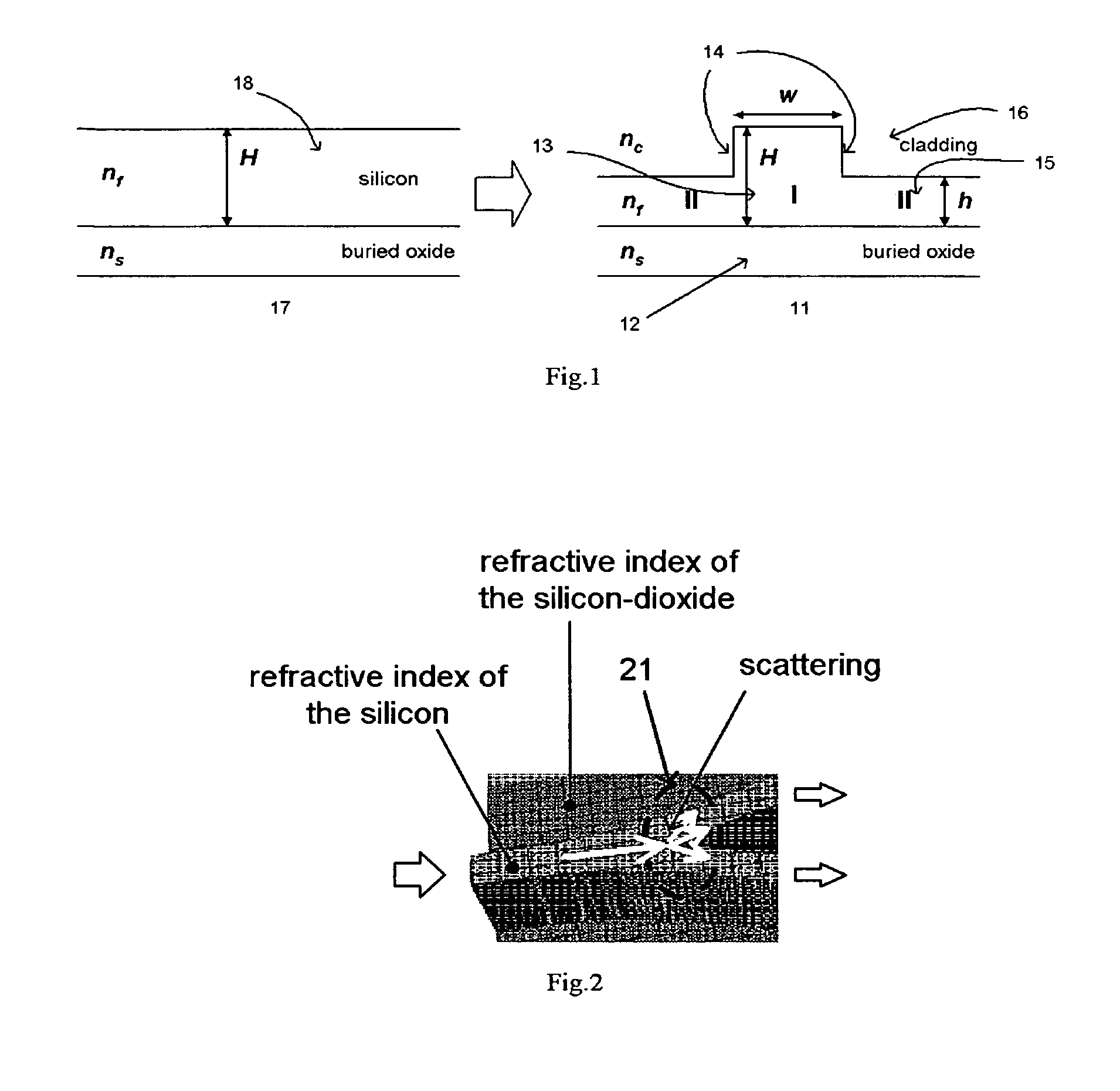
When the mode hits the junction, a significant scattering will occur and the field gets an abrupt disturbance.

Method used


Image

  • Single mode photonic circuit architecture and a new optical splitter design based on parallel waveguide mode conversion
  • Single mode photonic circuit architecture and a new optical splitter design based on parallel waveguide mode conversion
  • Single mode photonic circuit architecture and a new optical splitter design based on parallel waveguide mode conversion

Examples


Embodiment Construction

[0034]Single Mode Photonic Circuits (SMC) Architecture

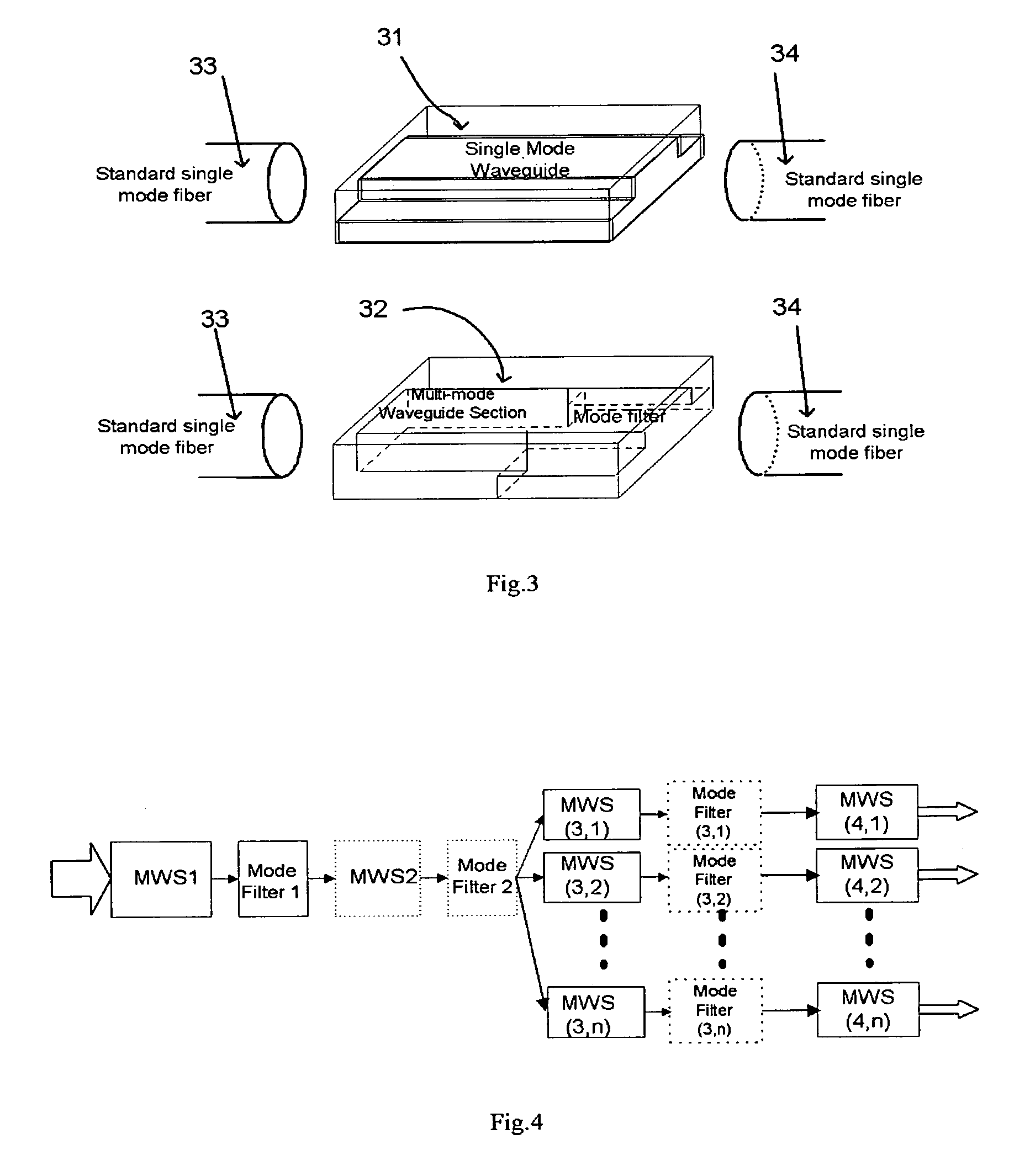
[0035]The first invented structure, or architecture, or a design approach, is the single mode photonic circuits (SMC) in which the multimode waveguide can be used. As we mentioned before, the whole PIC must be maintained as single mode operation, but it doesnhave to be achieved by the single mode waveguide. The idea is a new concept: single mode at system (circuit) level. As long as the whole circuit can only operate at one mode, the individual section can be constructed by multimode waveguides. A mode filter will be inserted after the multimode section. If designed correctly, the high order modes will not be excited in those multimode sections, and even they are, the mode filter will remove those high order components and keep the whole system at the single mode. In the ideal case, the high order mode excitation will never occur after the mode filter of the fiber-to-PIC coupling interface since only the main guiding mode is exci...


PUM


Abstract

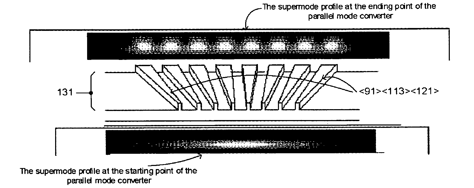
The new single mode circuit (SMC) architecture is invented for photonic integrated circuits (PIC). This architecture allows using multimode waveguides or structures to construct a single mode operated PIC. The multimode sections used in such SMC based PIC possess strong lateral confinement so that the PIC can have high circuit density and high optical performance at the same time. A parallel mode converter structure is also invented here. Based on this parallel mode converter, a low loss optical splitter can be constructed for high index contrast waveguide system.

Description

PRIOR PROVISIONAL PATENTS[0001]This utility patent application is based on, and claims the benefit of the following provisional patent:[0002]Appl. No. 60 / 810,865.[0003]Filing date: Jun. 5, 2006[0004]Title: Single mode photonic circuits based on multimode waveguide and a new optical splitter design based on parallel waveguide mode conversionBACKGROUND OF THE INVENTION[0005]In the past, photonic integrated circuits (PIC), which is also called planar lightwave circuits (PLC) or optical integrated circuits (OIC), are designed using single mode optical waveguide structures. The reasons of using single mode waveguide is to ensure that the whole circuits is within the single mode operation region, therefore, no high order modes will be excited both within the circuits and at the interface of the coupling to the outside world, usually to optical single mode fiber. If the waveguide is not single mode, when the higher order modes are excited, multiple guiding modes will propagate together alo...

Claims


Application Information

Patent Timeline
Patent Type & Authority Patents(United States)
IPC IPC(8): G02B6/12
CPCB82Y20/00G02B6/1223G02B6/14G02B6/30G02B2006/12195
Inventor LI, BING
Owner LI BING
Learn More