
Lifting sling having a tenacious coating with methods of manufacturing and monitoring the same

a technology of lifting slings and coatings, applied in the direction of load-engaging elements, transportation and packaging, etc., can solve the problems of damage to the material damage to the nylon and polyester type materials, etc., to improve the operation conditions and or suitability, improve the effect of ultraviolet light protection, and enhance the effectiveness of the lifting sling

Inactive Publication Date: 2010-03-02
CARMICHAEL DANIEL T
View PDF24 Cites 21 Cited by
  • Summary
  • Abstract
  • Description
  • Claims
  • Application Information

AI Technical Summary

Benefits of technology

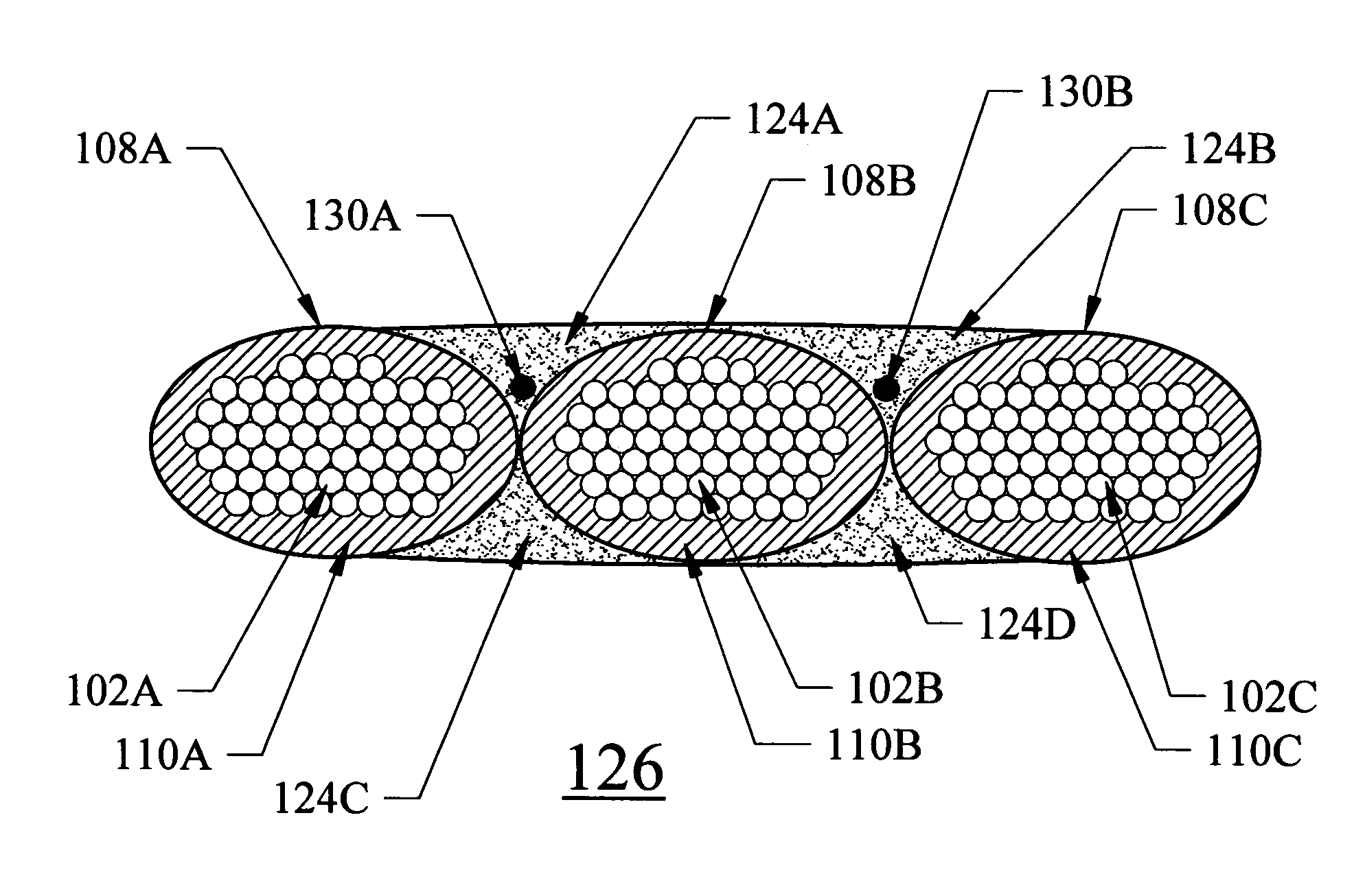
"The present invention relates to improving the lifting sling by coating it with a polyurea elastomer, polyurethane, or hybrid polyurethane-polyurea elastomer. The coating can enhance the lifting sling's effectiveness and improve its operational conditions and suitability for use. The coating can also protect the lifting sling from damage caused by ultraviolet light, elevated temperatures, and fire retards. Additionally, the invention relates to using a multi-coat multi-pigment coating method to better determine the integrity of the surface coating of the lifting sling during use and to better determine when the surface coating requires repair or replacement. The invention also relates to coating both the lifting sling core and cover or sheath, and to forming a multi-core lifting sling by positioning a plurality of single cores in a parallel alignment and applying a seaming coat to secure them together. The invention also relates to embedding a safety core along the length of the lifting sling core and utilizing the coating material to secure the safety core to the lifting sling core."

Problems solved by technology

Such ultraviolet light rays can damage lifting sling materials, in particular damaging nylon and polyester type materials.

Method used


Image

  • Lifting sling having a tenacious coating with methods of manufacturing and monitoring the same
  • Lifting sling having a tenacious coating with methods of manufacturing and monitoring the same
  • Lifting sling having a tenacious coating with methods of manufacturing and monitoring the same

Examples


Embodiment Construction

[0089]The preferred embodiments of the present invention will now be described in detail with reference to the Figures. Although the lifting slings, systems, and methods of the present invention will be described in connection with these preferred embodiments and drawings, it is not intended to be limited to the specific form set forth herein, but on the contrary, it is intended to cover such alternatives, modifications, and equivalents, as can be reasonably included within the spirit and scope of the invention.

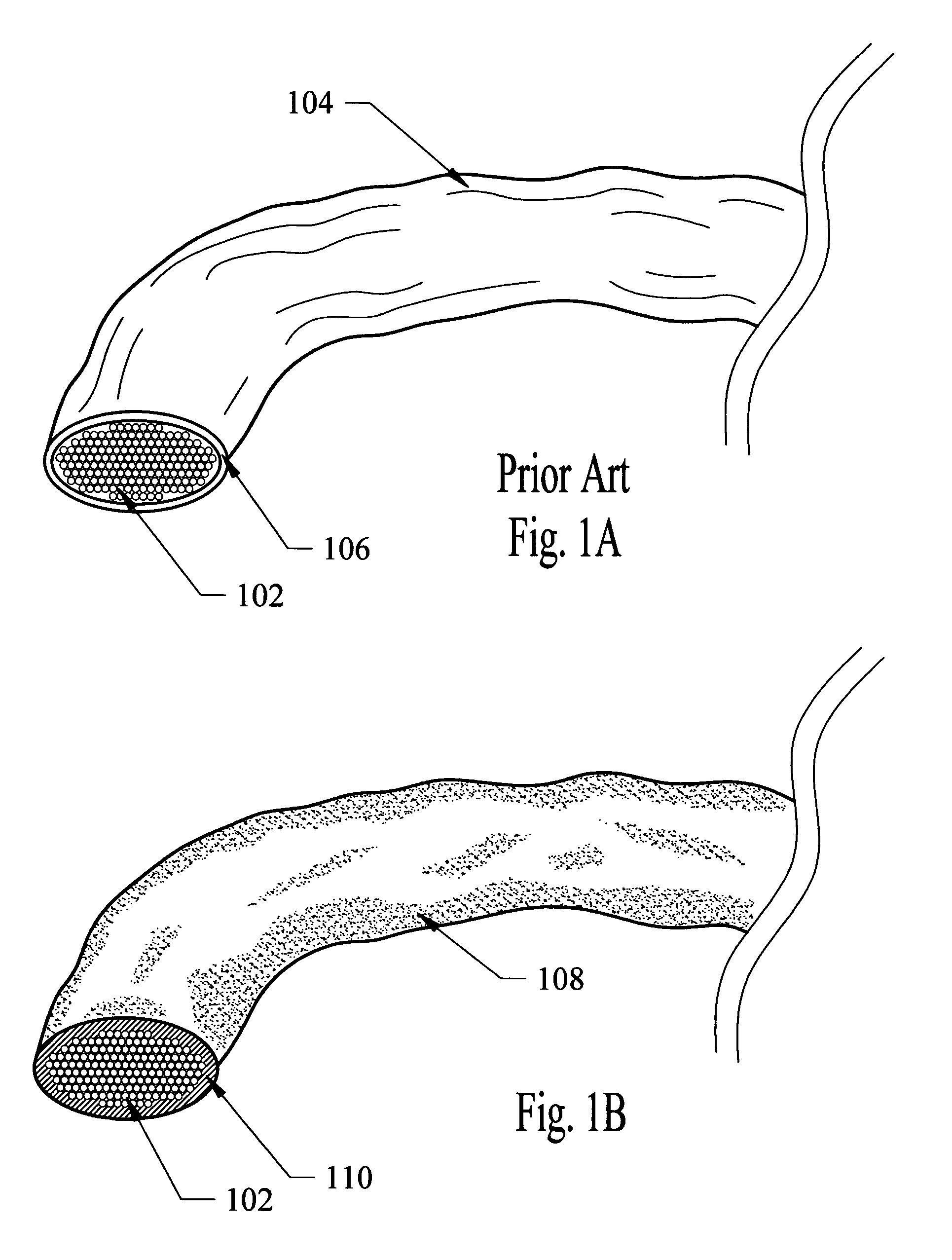
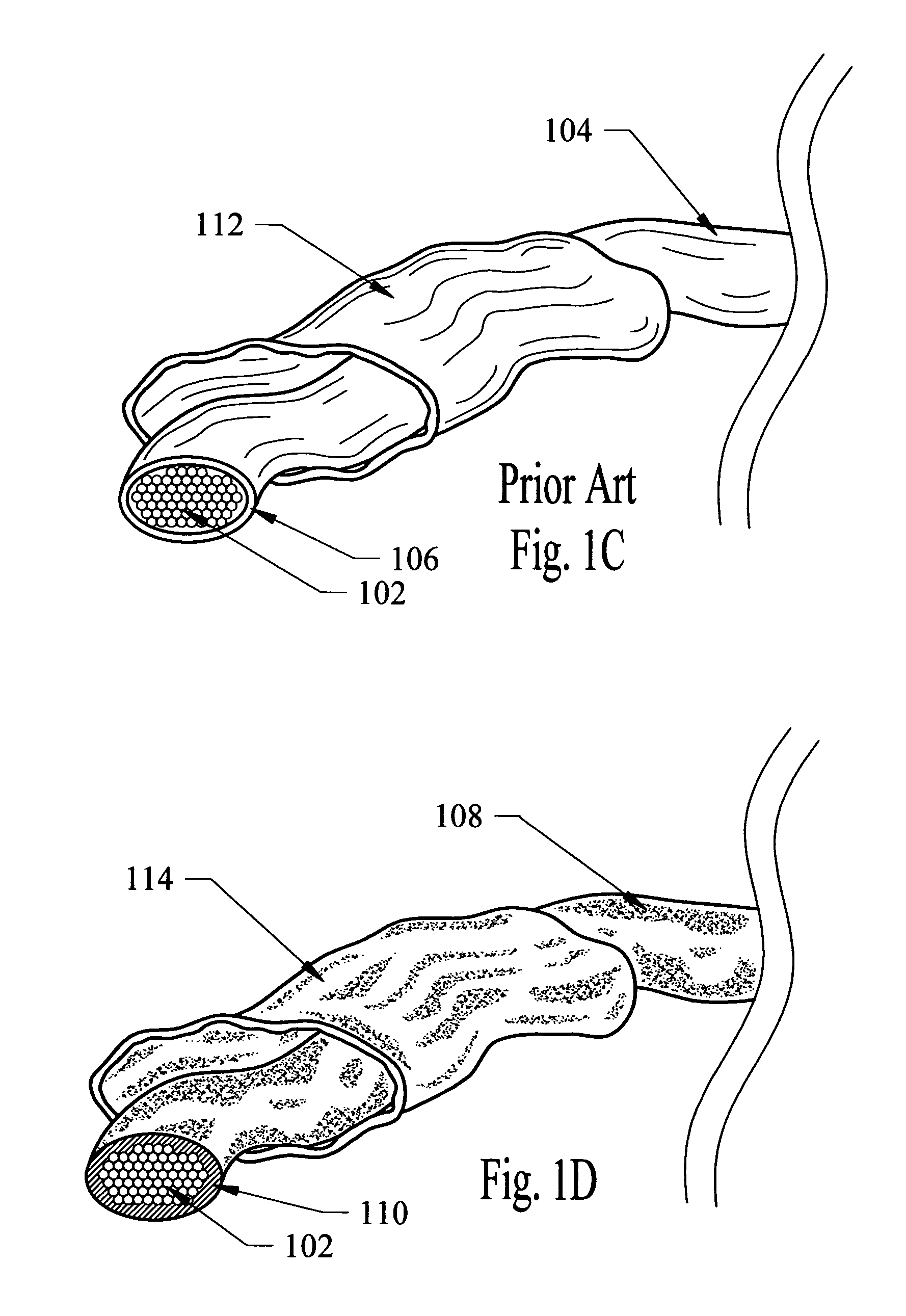
[0090]Referring to FIG. 1A there is shown a cross sectional view of a lifting sling core having a protective sheath. FIG. 1A depicts an example of a prior art style or type of lifting sling. In this regard, the lifting sling core 102 is surrounded by a protective sheath 106. The lifting sling combination of the core 102 and sheath 106 can be referred to as prior art lifting sling 104. In an attempt to protect the core 102 from operational and force related traumas or damage c...


PUM


Abstract

The present invention relates to coating of lifting slings with a polyurea elastomer, polyurethane, or hybrid polyurethane-polyurea elastomer. In addition, optionally the coating material can include one or more additives such as a catalyst, stabilizer, pigment, fire retardant, or other additives. In the present invention use of additives can enhance the lifting slings effectiveness and improve the operational condition and or suitability for use of the lifting sling. The present invention also relates to the ability to form a multi-core sling from a plurality of single cores. More specifically, the single cores can be tenaciously bonded together with the coating material to form a multi-core lifting sling. The present invention also relates to embedding a safety core along the length of the lifting sling core. The safety core allows monitoring of certain operational parameters related to the lifting sling by way of an indicator and or electronic system.

Description

TECHNICAL FIELD OF THE INVENTION[0001]The present invention relates to coating of lifting slings with a polyurea elastomer, polyurethane, or hybrid polyurethane-polyurea elastomer. In addition, optionally the coating material can include one or more additives such as a catalyst, stabilizer, pigment, fire retardant, or other additives. In the present invention use of additives can enhance the lifting slings effectiveness and improve the operational condition and or suitability for use of the lifting sling.[0002]The present invention also relates to the ability to form a multi-core lifting sling from a plurality of single cores. More specifically, the single cores can be tenaciously bonded together with the coating material to form a multi-core lifting sling. In this regard, a multi-core lifting sling can be manufactured by positioning a plurality of single cores in a parallel alignment, and then applying a seaming coat of the polyurea elastomer, polyurethane, or hybrid polyurethane-p...

Claims


Application Information

Patent Timeline
Patent Type & Authority Patents(United States)
IPC IPC(8): B66C1/12
CPCB66C1/12B66C1/18
Inventor CARMICHAEL, DANIEL T.
Owner CARMICHAEL DANIEL T
Learn More