Hearing aid system

a technology of hearing aids and cables, applied in the field of hearing aid systems, can solve the problems of poor connection efficiency of direct bone conductors, and difficulty in mounting and accessing, and achieve the effect of convenient mounting and access

Active Publication Date: 2010-03-02
OTICON MEDICAL
View PDF6 Cites 25 Cited by
  • Summary
  • Abstract
  • Description
  • Claims
  • Application Information

AI Technical Summary

Benefits of technology

[0008]The present invention provides an effective solution to the above-outlined problems with implantable direct bone conduction hearing aids. More particularly, the direct bone conduction hearing aid system of the present invention has a vibrator that is placed in an implanted vibrator unit. The implanted vibrator unit is positioned in the mastoid cavity. A mounting arm extends from the lateral end of the implanted vibrator unit to a lateral side (i.e., the outside) of the skull bone over part of the skull bone surface where the mounting arm is fixated to the skull bone via an anchoring fixture. The anchoring fixture is easy to mount and access since it is mounted to the skull bone from a lateral position. The anchoring fixture is preferably a screw-shaped osseointegrating fixture that is screwed into the skull through the skull bone surface.
[0009]In this way the vibrator that needs some space is located in the mastoid cavity where there is room for it. However, via the mounting arm, the vibrator is fixated to the cortical skull bone that has a high bone quality and where the anchoring fixture is easy to mount and access.

Problems solved by technology

A traditional bone conductor where the vibrations have to go through the skin to reach the skull bone is less efficient than a direct bone conductor since the vibrations will be damped when going through the skin.
These patients have often problems with skin infections due to the permanent skin-penetrating abutment.
The problem with this anchoring is that the bone in this area is very soft, so the anchoring will be quite weak.
If the anchoring fixture is placed deep in the mastoid cavity, it will also be difficult to get access to the anchoring fixture if the vibrator unit needs to be removed.
Since it is very difficult to do a very flat vibrator, the aesthetics of this solution will not be very good.
To do the whole implantable arrangement in one unit is also not a good solution since the vibrator, which is usually an electromagnetic vibrator, should not be placed together with the inductive energy transmission coil since it may interfere with the function of the inductive energy transmission.

Method used


Image

  • Hearing aid system
  • Hearing aid system
  • Hearing aid system

Examples


Embodiment Construction

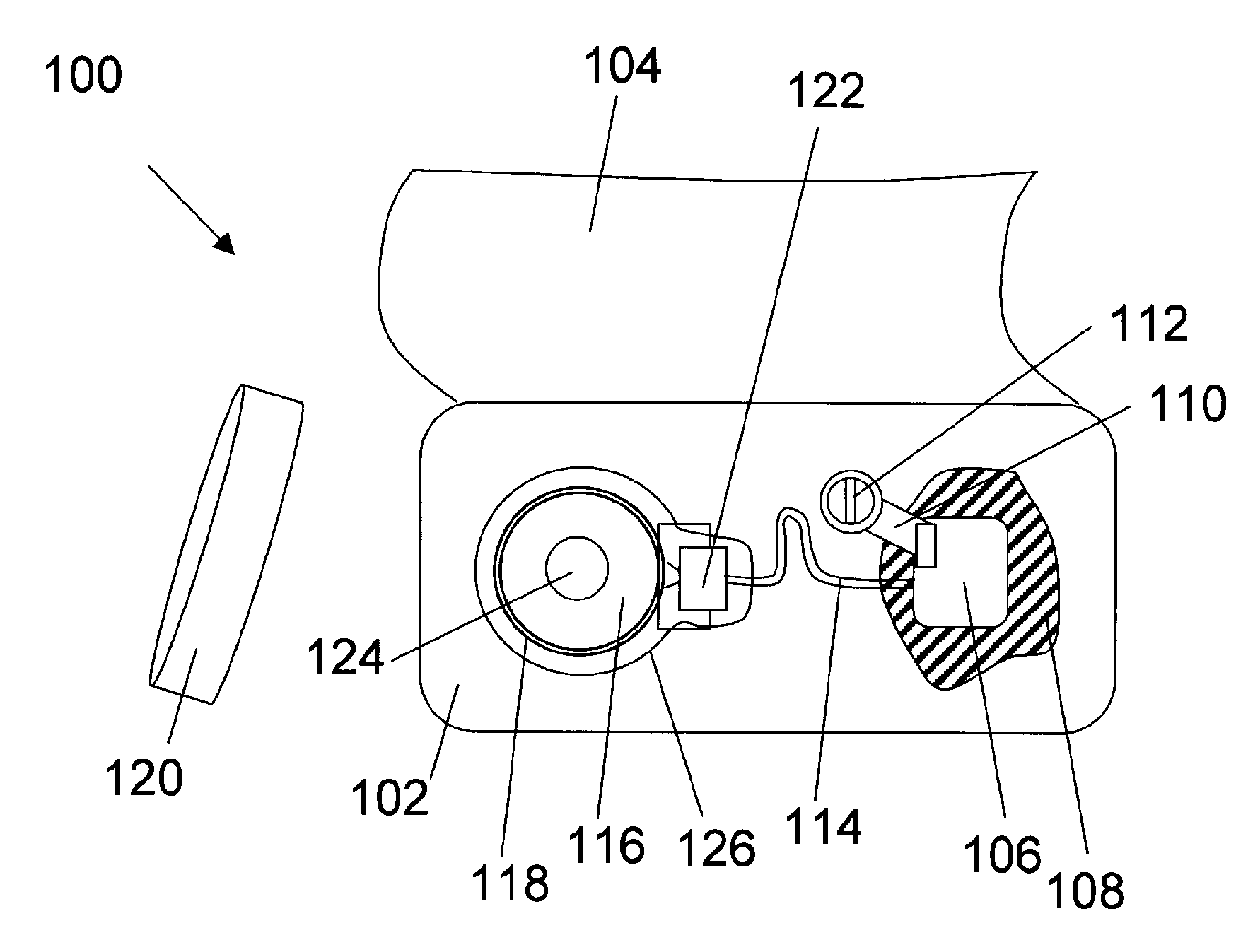
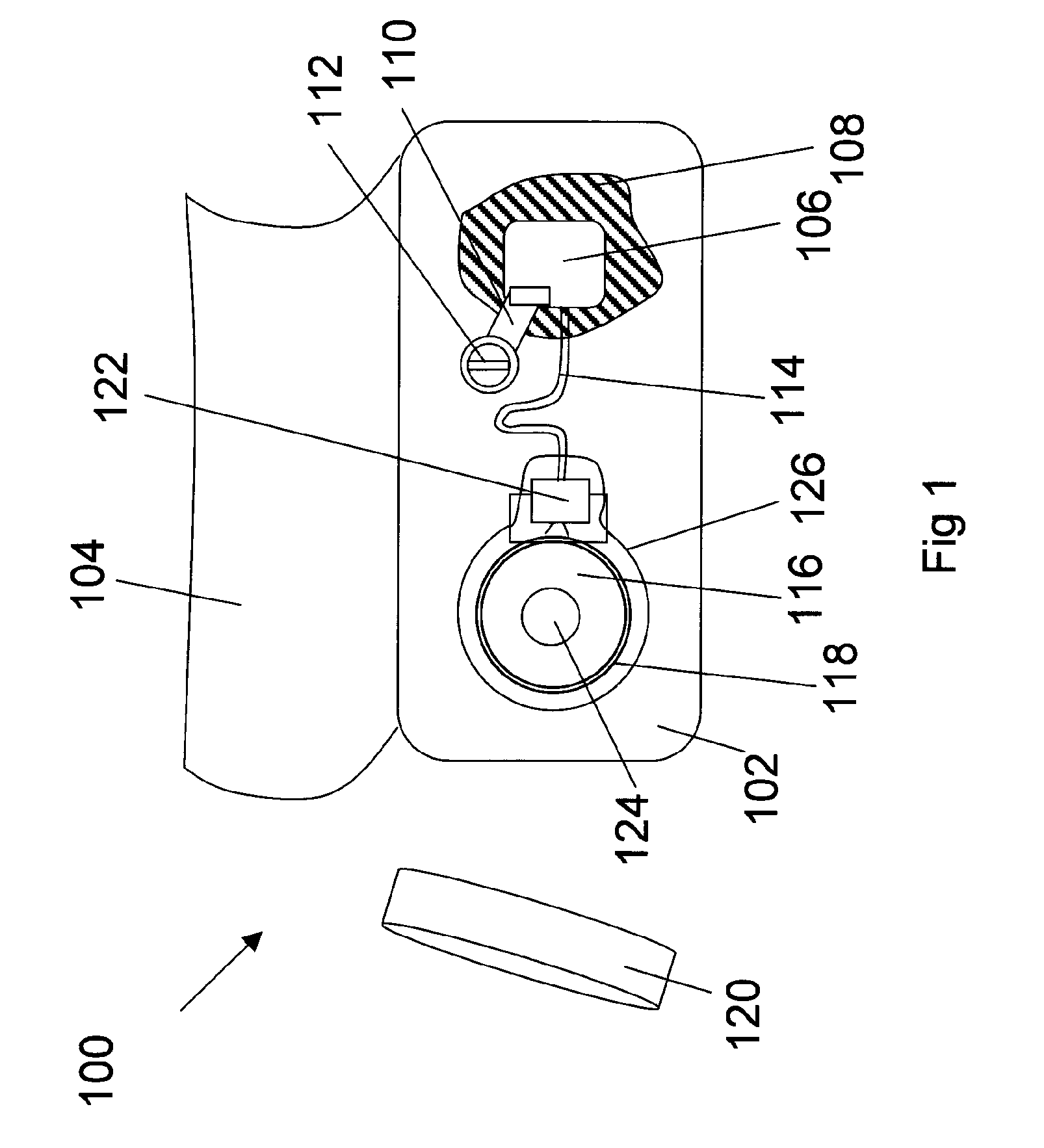
[0042]FIG. 1 is a side view of the hearing aid system 100 of the present invention. A skull bone 102 is visible since a skin flap 104 has been folded away for the surgery. An implanted vibrator unit 106 is mounted in a mastoid cavity 108. A mounting arm 110 extends from the implanted vibrator unit 106 to an anchoring fixture 112. The anchoring fixture 112 is mounted through a hole (not seen) in the mounting arm 110. The anchoring fixture 112 is screwed into the skull bone 102 from a lateral direction, i.e., from the side of the skull. A vibrator supply cable 114 goes from the implanted vibrator unit to an implanted energy-receiving unit 116. The implanted energy-receiving unit 116 has an energy-receiving inductive coil 118 that can receive electromagnetic power by wireless induction from an external transmitter unit 120. The implanted electronics 122 is placed in the implanted energy-receiving unit 116. The implanted energy-receiving unit 116 has a magnetic portion 124 so that the e...


PUM


Abstract

A direct bone conduction hearing aid system for generating direct bone conduction vibration includes a vibrator that is placed in an implanted vibrator unit and an implanted energy-receiving unit that has an energy-receiving inductive coil. A vibrator supply cable connects the implanted energy-receiving unit to the implanted vibrator unit. A mounting arm connects the implanted vibrator unit with an anchoring fixture that is anchored to the skull bone through the skull bone surface. The implanted vibrator unit is positioned in the mastoid cavity. The mounting arm is positioned laterally to the implanted vibrator unit and the bone fixation portion of the anchoring fixture.

Description

TECHNICAL FIELD[0001]The present invention relates to a hearing aid system for providing direct bone conduction hearing.BACKGROUND OF THE INVENTION[0002]Bone conduction is the principle of transmitting vibrations via the skull bone to the inner ear, i.e., the cochlea. For a bone conduction hearing aid the vibrations are transmitted through the skull bone, and since the cochlea is a winding in the bone, the vibrations go directly to the cochlea. This means that for bone conduction the normal transmission chain with the ossicular bones, for example the stapes, is not directly involved in the transmission of the vibrations to the cochlea. Hearing aids that for example connect to the middle ear ossicular bones are not bone conduction hearing aids.[0003]A direct bone conduction hearing aid is a type of bone conduction hearing aid where the vibrator of the hearing aid is firmly connected to the skull bone so that the vibrations from the vibrator do not have to go through the skin to reach...

Claims


Application Information

Patent Timeline
Patent Type & Authority Patents(United States)
IPC IPC(8): H04R25/00
CPCH04R25/554H04R25/606H04R25/456H04R2460/13H04R2225/67
Inventor WESTERKULL, PATRIK
Owner OTICON MEDICAL
Why Eureka
Try Eureka