
Device and process for quantitative assessment of the three-dimensional position of two machine parts, shafts, spindles, workpieces or other articles relative to one another

a technology of three-dimensional positioning and positioning of two machines or machine parts, applied in measurement devices, instruments, using optical means, etc., can solve the problems of saving an enormous amount of work time by their use, and achieve the effect of improving the known process and device, extending the measurement range, and improving the precision of such a devi

Active Publication Date: 2010-03-02
PRUTECHNIK DIETER BUSCH AG
View PDF12 Cites 21 Cited by
  • Summary
  • Abstract
  • Description
  • Claims
  • Application Information

AI Technical Summary

Benefits of technology

"The present invention provides a device and process for improving the precision and measurement range of a device by using a repeatedly fanned light beam and multiple linear optoelectronic sensor arrays. The device can measure the displacement of machine parts, metrological devices, and even in coordinate measurement devices or measurement robots. The device has the advantages of enlarged measurement range and increased optical resolution. The use of the device can also be cost-effective and efficient in terms of data preparation and detection of additional rotary angle coordinates. The invention can be used in various applications such as building construction or underground construction."

Problems solved by technology

Processes and devices of a similar type have been successfully used for several years in the assessment of the three-dimensional positioning and orientation of two machines or machine parts relative to one another and have been characterized in that an enormous amount of work time has been saved by their use.

Method used


Image

  • Device and process for quantitative assessment of the three-dimensional position of two machine parts, shafts, spindles, workpieces or other articles relative to one another
  • Device and process for quantitative assessment of the three-dimensional position of two machine parts, shafts, spindles, workpieces or other articles relative to one another
  • Device and process for quantitative assessment of the three-dimensional position of two machine parts, shafts, spindles, workpieces or other articles relative to one another

Examples


Embodiment Construction

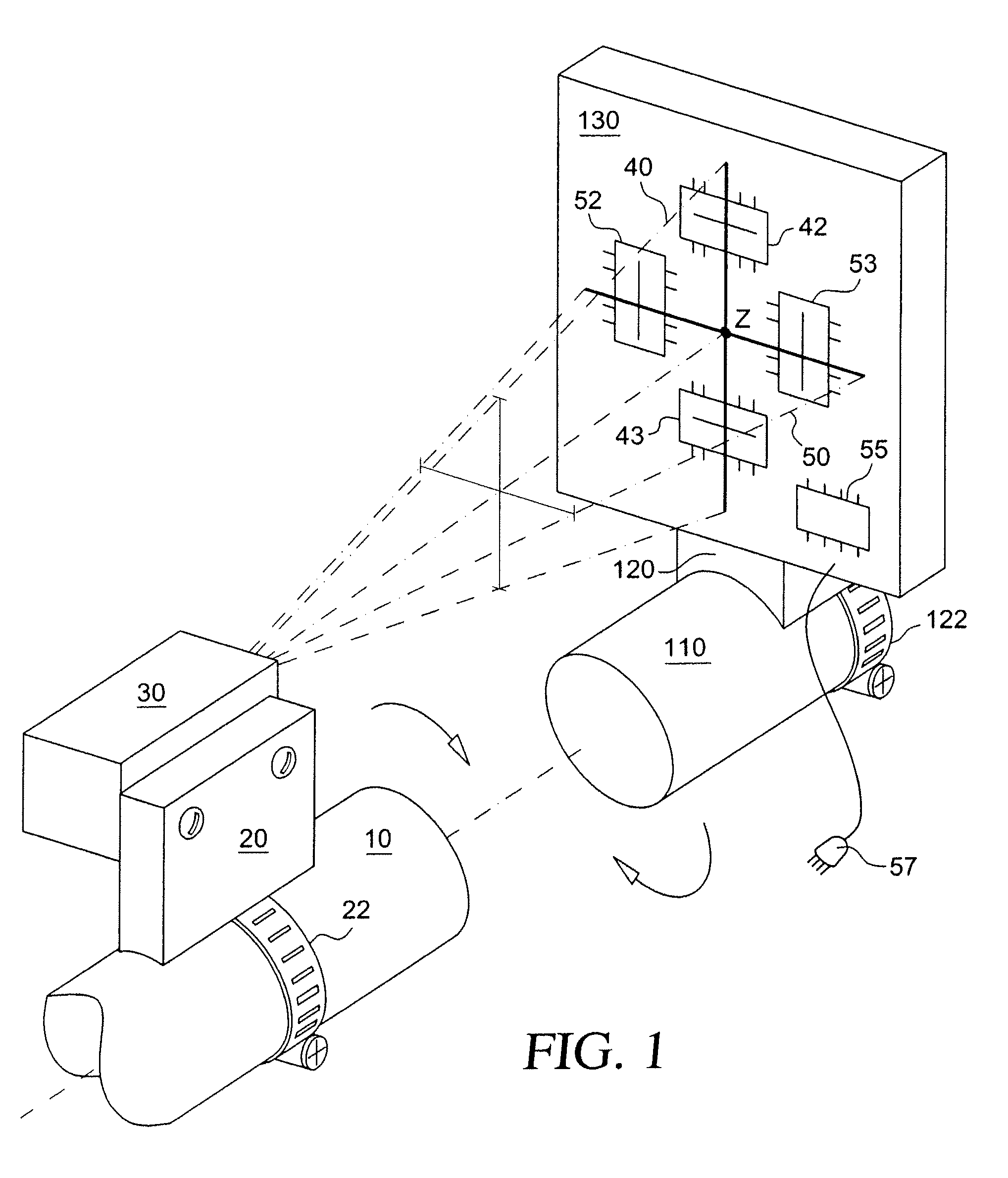
[0039]As shown schematically in FIG. 1, a metrological system in accordance with the invention can be accommodated in two separate housings 30, 130. There are holding or clamping devices 22, 122 so that application to the shaft ends 10, 110 of machines is possible in the known manner.

[0040]Within the housing 30, there is a device for producing two laser light planes which are oriented forward and which are preferably oriented at right angles to one another. As already mentioned, this special laser light can be produced by means of diffraction gratings, a hologram or a microlens arrangement.

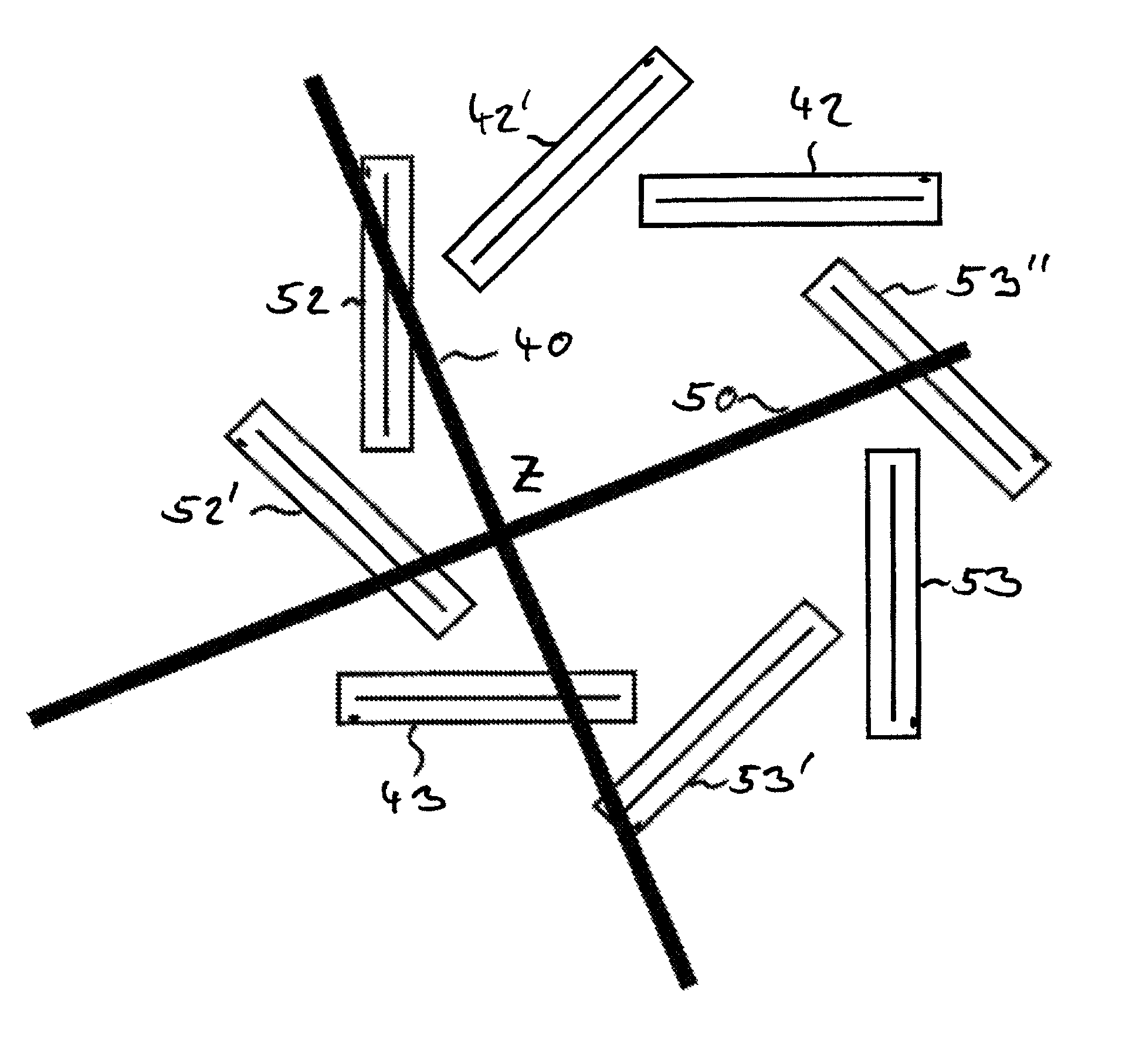
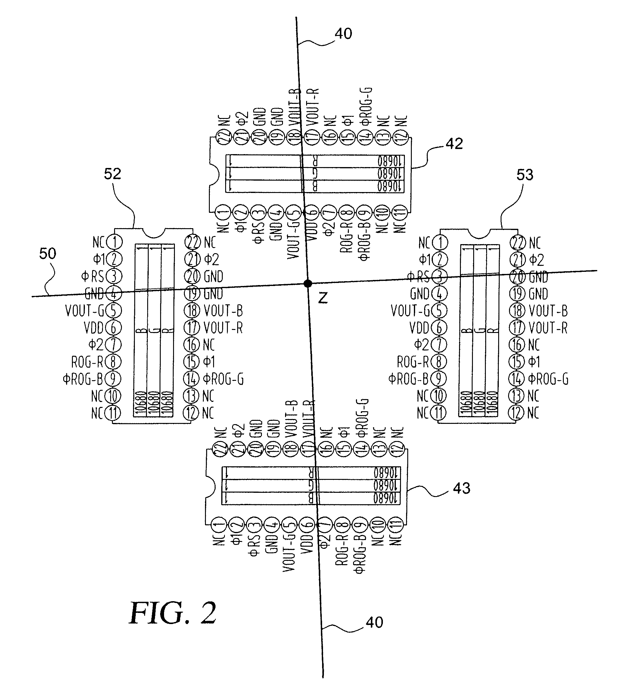
[0041]Therefore, the device which is connected to the housing 130 represents a receiving device especially for an incident laser beam or light beam with an essentially crosshair-shaped cross section. The receiving elements are line sensors (linear arrays) or position sensitive detectors (PSDs) 42, 43, 52 and 53 which are located roughly on the sides of a square. The origin of the coordinate system...


PUM


Abstract

An apparatus and a method that can be used for qualitative or quantitative determination of the three-dimensional location of two bodies relative to one another which can be used, for example, to determine the mutual position of two bodies according to angular or translational coordinates. Furthermore, the apparatus and method can be used in a measurement robot or in a coordinate measurement device. The device composed of a device for emitting a light beam which is fanned in several planes and at least three, preferably four or more, optoelectronic line sensors or linear sensors for determination of the incidence points of the light beam which has been flared in several planes on the line sensors or an upstream target surface.

Description

BACKGROUND OF THE INVENTION[0001]1. Field of the Invention[0002]The invention relates to a process and devices for quantitative assessment of the three-dimensional positioning and orientation of two machines or machine parts relative to one another, such as, for example, shafts, machine tool spindles, workpieces or other physical articles. The invention is likewise suited to quantitatively measuring or assessing the alignment of two cylindrical objects which are to be aligned to one another, for example, pipes or pipelines. Furthermore, the device is suited to use as a sensor in a coordinate measurement device or a measurement robot. Moreover, the invention is suited for use as a measurement means in ranging tasks in building construction and underground construction, especially in tunnel building.[0003]2. Description of Related Art[0004]Processes and devices of a similar type have been successfully used for several years in the assessment of the three-dimensional positioning and or...

Claims


Application Information

Patent Timeline
Patent Type & Authority Patents(United States)
IPC IPC(8): G01B11/14
CPCG01B11/272
Inventor HERMANN, MICHAEL
Owner PRUTECHNIK DIETER BUSCH AG
Learn More