Adaptor for wireless network

Inactive Publication Date: 2010-03-02
138 EAST LCD ADVANCEMENTS LTD
View PDF13 Cites 13 Cited by
  • Summary
  • Abstract
  • Description
  • Claims
  • Application Information

AI Technical Summary

Benefits of technology

[0009]The object of the present invention is thus to facilitate sett

Problems solved by technology

Another example is that the characteristics of one wireless network are unsuitable for a

Method used


Image

  • Adaptor for wireless network
  • Adaptor for wireless network
  • Adaptor for wireless network

Examples


Example

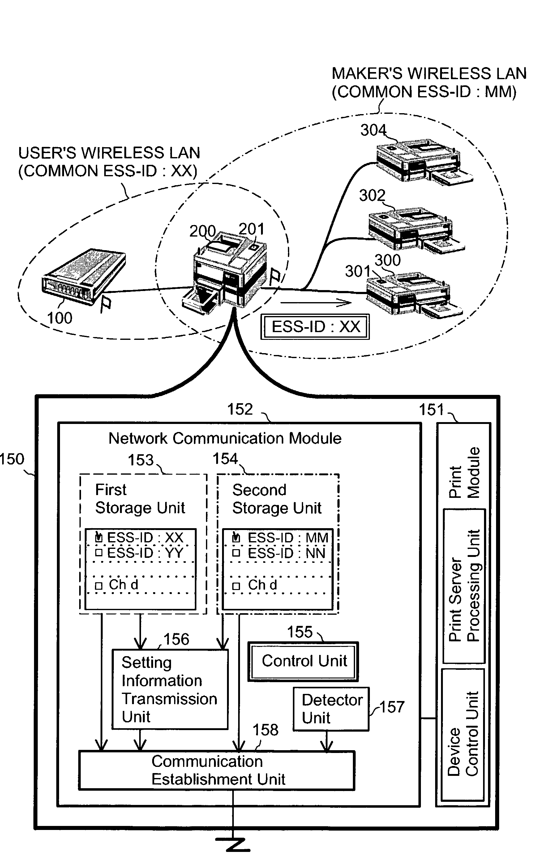
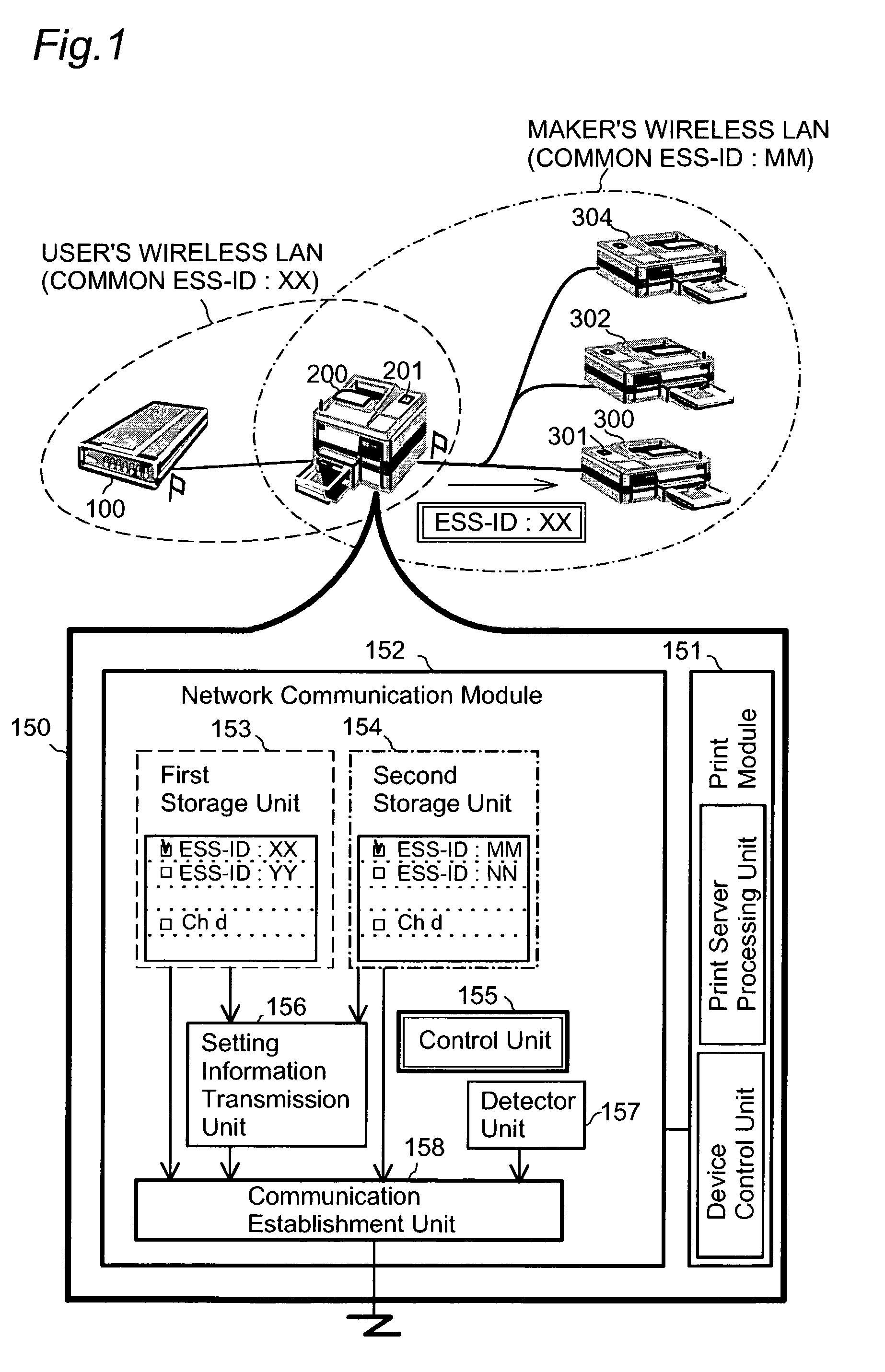
[0052]FIG. 1 schematically illustrates the configuration of a system in a first embodiment of the present invention. A printing device 200 in the system includes an adaptor used for connection with a wireless network. The adaptor functions to connect the printing device 200 with both a user's wireless LAN and a maker's wireless LAN. Printers 300 and 302, and 304 are additional devices to be newly connected to the user's wireless LAN. The printing device 200 transmits setting information used for connection with the user's wireless LAN to these additional devices by means of the maker's wireless LAN.

[0053]The user's wireless LAN is constructed as a wireless network based on the infrastructure system by the function of an access point 100 as a relay station. A value ‘XX’ is set as an initial value of ESS-ID in each of the devices belonging to the user's wireless LAN. Setting information ESS-ID ‘XX’ is required for connection with the user's wireless LAN. The access point 100 functioni...

Example

[0083]The following describes a second embodiment of the present invention, where the printing device transmits setting information by utilizing a direct wireless communication system in combination. In the first embodiment, communication of the infrastructure system is applied for the maker's wireless LAN. But the maker's wireless LAN is not restricted to this system. The advantages of the direct wireless communication system are convenience and simplicity in establishment of a network, although the direct wireless communication network has a disadvantage, the less stability of connection. A diversity of techniques may be applicable for the direct wireless communication system. In this embodiment, the Ad Hoc system is applied for direct wireless communication.

[0084]FIG. 4 is a timing chart showing the timings of a process of utilizing the Ad Hoc system in combination in the second embodiment. The system configuration of the second embodiment is identical with that of the first embo...

Example

[0095]The following describes a process of acquiring the ESS-ID as a third embodiment of the present invention. A printing device 200B of the third embodiment acquires the ESS-ID and enters the user's wireless LAN with the acquired ESS-ID.

[0096]FIG. 6 schematically illustrates the configuration of a system in the third embodiment. The printing device 200B is a device newly entering the user's wireless LAN. The user's wireless LAN is constructed by the functions of the access point 100 as the relay station. An existing printer 400 and a personal computer 500 are devices that currently belong to the user's wireless LAN. The printing device 200B acquires the ESS-ID for entering the user's wireless LAN from the existing printer 400 or the personal computer 500.

[0097]The printing device 200B starts an ESS-ID acquisition process in the case where the ESS-ID stored therein is an initial value. For example, the printing device 200B may utilize a flag representing a factory shipment state an...


PUM


Abstract

A printing device of the present invention has an additional function of switching over connection with two wireless networks. The printing device enters a user's wireless LAN based on first setting information, while establishing connection with a maker's wireless LAN based on second setting information to communicate with a printer, which is one of additional devices newly entering the user's wireless LAN. In response to a requirement from the printer, the printing device temporarily disconnects from the user's wireless LAN and enters the maker's wireless LAN to transmit setting information relating to the user's wireless LAN to the printer. This arrangement desirably relieves the labor of the user for settings in the additional devices to establish connection with the wireless network.

Description

BACKGROUND OF THE INVENTION[0001]1. Field of the Invention[0002]The present invention relates to an adaptor used for connection with a wireless network[0003]2. Description of the Related Art[0004]Advancement in recent network technologies has actualized networks to which computers, printing devices, and a diversity of other devices are connected, for example, the Internet and various LANs (Local Area Networks). The network technologies actualize wireless communication by utilizing the functions of adaptors built in respective devices, as well as wired communication. The wireless communication eliminates the troubles in setting, connecting, and changing cables.[0005]One method of attaining a wireless network is the infrastructure system utilizing a star-shaped network where terminals called stations (ST) are concentrically connected by a relay station called an access point (AP). In the infrastructure system, the access point that transmits a beacon continuously manages the group of ...

Claims


Application Information

Patent Timeline
IPC IPC(8): H04W4/00H04H60/09H04L12/28H04L12/56H04N1/46G06F3/12H04W48/18H04W84/12
CPCH04L12/5692H04W28/18H04L67/14H04M2215/32H04W8/005H04W36/14H04W48/08H04W48/18H04W76/02H04W84/12H04W84/18H04W88/06H04W92/02H04W76/10
Inventor GASSHO, KAZUHITOSHIOHARA, SUSUMU
Owner 138 EAST LCD ADVANCEMENTS LTD
Why Eureka
Try Eureka