
Fork-Type Covered Stent

Active Publication Date: 2017-05-11
LIFETECH SCIENTIFIC (SHENZHEN) CO LTD
View PDF60 Cites 10 Cited by
  • Summary
  • Abstract
  • Description
  • Claims
  • Application Information

AI Technical Summary

Benefits of technology

The patent text describes a new design for a stent graft that helps to improve blood flow in the body. The design includes a main body and a side branch that can be connected together. In one embodiment, the stent graft has smoothly rounded tails on the end support bars. This design helps to prevent the covering film from retracting and allows for the smooth entrance of a guidewire. Additionally, the first bare stent is attached to the vertex angle area, which helps to support the side branch and avoid the retraction of the covering film. This simplifies the preparation of the bare stent and allows for easier adjustment of the waveform. Overall, this design improves the efficiency and ease of use of stent grafts in the body.

Problems solved by technology

Based on the above, there is a need to provide a bifurcated stent graft to address the problems that the support force at the boundary between the body and the side branch is insufficient, and that it is difficult for the guidewire to enter.

Method used


Image

  • Fork-Type Covered Stent
  • Fork-Type Covered Stent
  • Fork-Type Covered Stent

Examples


Embodiment Construction

[0051]In order to fully understand the invention, the bifurcated stent graft will now be described more fully with reference to the related drawings. Preferred embodiments of the bifurcated stent grafts are shown in the drawings. However, the bifurcated stent graft can be achieved in many different ways and is not limited to the embodiments described herein. Conversely, these embodiments are provided so that this disclosure of the bifurcated stent graft will be more thorough and complete.

[0052]It will be understood that when an element is referred to as being “fixed on” another element, it can be directly on the other element or intervening elements may also be present. When an element is referred to as being “connected with” another element, it can be directly connected with the other element or intervening elements may also be present. The terms “vertical”, “horizontal”, “left”, “right” and the like are used herein for the purpose of explanation only and not intended to represent ...


PUM


Abstract

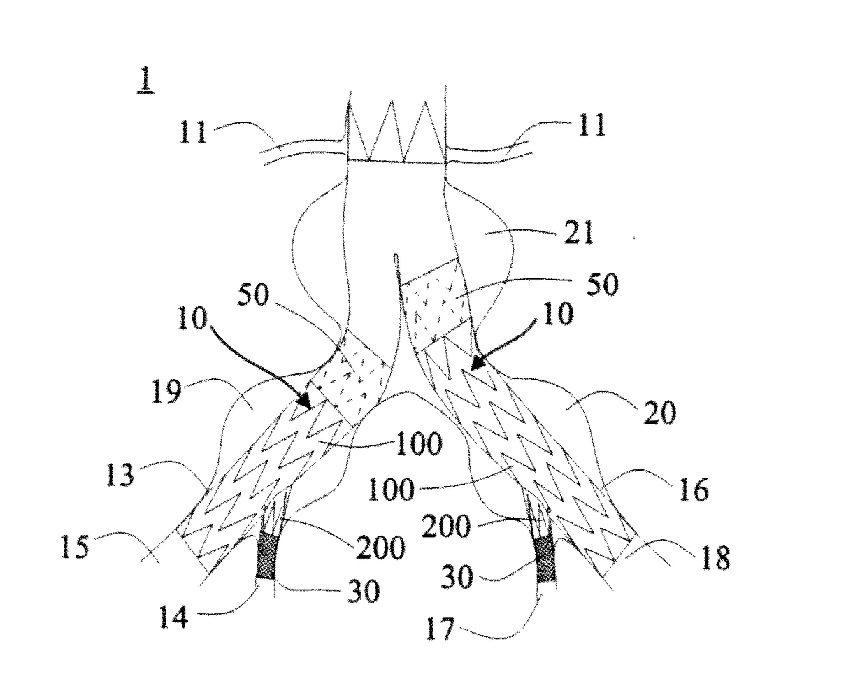
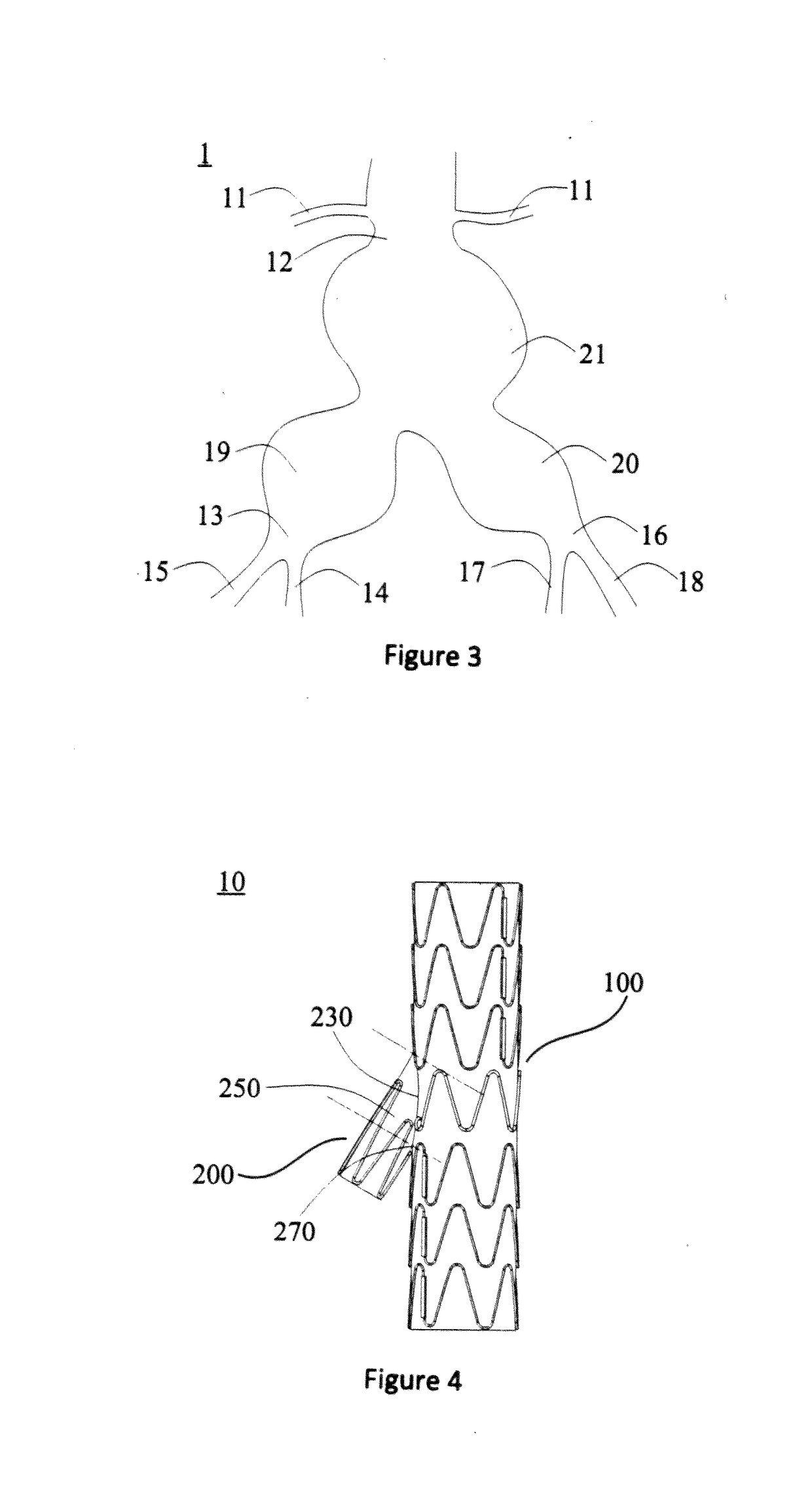
A bifurcated stem graft (10) comprises a body (100) and a side branch (200) that forms an acute angle with the body (100). The side branch (200) comprises a covering film (220) and a first bare stent (240) only disposed on the covering film (220). Part of the first bare stent (240) is positioned adjacent a boundary line (230) of the body (100) and the covering film (220) and is located in a vertex angle area (250) of the acute angle. Due to the fact that part of the first bare stem (240) is attached to the vertex angle area (250), after the stem (10) is released, the self-expanded part of the first bare stent (240) enables the vertex angle area (250) of the side branch (200) to be effectively supported, the covering film is not prone to shrinkage, and a leading wire can enter easily. Meanwhile, a special bare stent attached to the vertex angle area (250) does not need to be additionally disposed on the first bare stent (240), and thus the technology for preparing the bare stem is simplified; furthermore, the first bare stent (240) is only disposed on the side branch (200) and does not need to span the connecting part of the body (100) and the side branch (200), and thus the waveform can be shaped easily.

Description

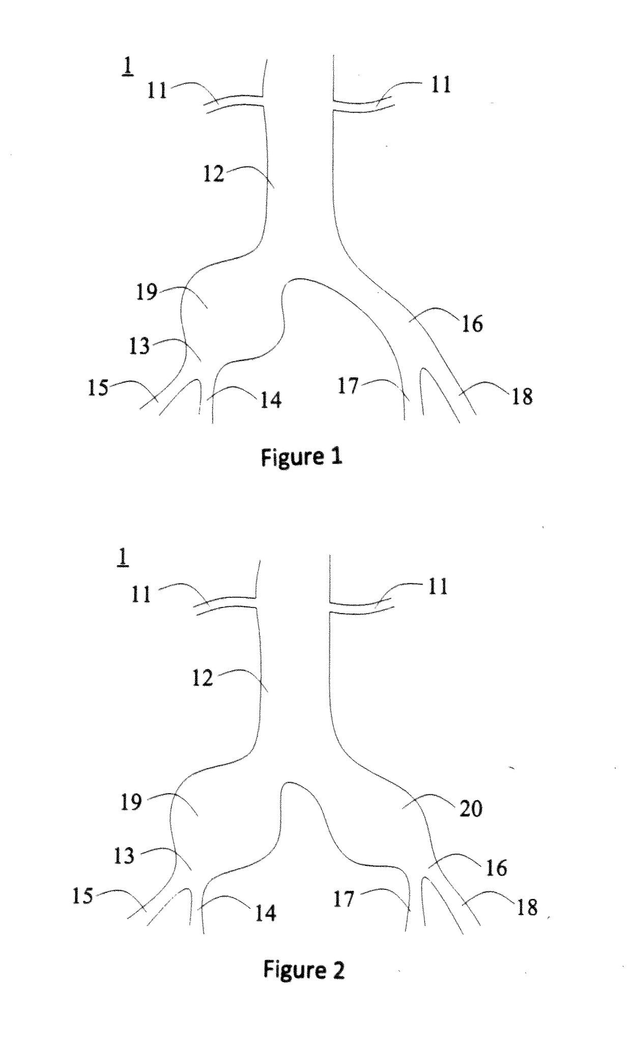
TECHNICAL FIELD[0001]The present invention relates to the technical field of medical devices, particularly to a bifurcated stent graft.BACKGROUND[0002]Aneurysm is a permanent limitation expansion of the blood vessel and it is called an aneurysm when the vessel diameter is increased by more than 50% of its normal size, If an aneurysm is in the abdominal aorta, an abdominal aortic aneurysm is formed. Iliac aneurysm is usually defined as the case that the local extension of the iliac artery diameter exceeds 1.5 cm. The iliac aneurysm is divided into isolated iliac aneurysm (see FIG. 1), independent iliac aneurysm (see FIG. 2), and iliac aneurysm accompanied by abdominal aortic aneurism (see FIG. 3). In 75% of the cases, iliac aneurysm is associated with abdominal artery. There are about 7.5% of the cases being isolated iliac aneurysm. The remaining aneurysm is the independent iliac aneurysm. In the United States, about 15,000 people die of abdominal aortic aneurysm (abdominal aortic an...

Claims


Application Information

Patent Timeline
IPC IPC(8): A61F2/07A61F2/856A61F2/915
CPCA61F2/07A61F2/915A61F2002/828A61F2002/065A61F2/856A61F2/89A61F2002/061A61F2002/075A61F2230/0054A61F2250/0037A61F2/06
Inventor WANG, YONGSHENGLIU, CAIPINGZHANG, DEYUANGUO, WEI
Owner LIFETECH SCIENTIFIC (SHENZHEN) CO LTD
Learn More