Step-up converter

Active Publication Date: 2008-09-04
PANASONIC SEMICON SOLUTIONS CO LTD
View PDF7 Cites 10 Cited by
  • Summary
  • Abstract
  • Description
  • Claims
  • Application Information

AI Technical Summary

Benefits of technology

[0008]Accordingly, an object of the present invention is to provide a current-mode control step-up converter capable of reducing the minimum duty ratio to zero or a sufficiently small value and facilitating the setting of the maximum duty ratio.

Problems solved by technology

The existence of the minimum duty ratio in the step-up converter causes a problem of impairing the stability of the output when the input and output voltages are close to each other.
Furthermore, the step-up ratio has an upper limit owing to the influence of resistance components including the resistances of the main switch and other components during conduction and wiring resistances, and it is necessary to set the maximum duty ratio so that the step-up ratio does not reach this upper limit.

Method used


Image

  • Step-up converter
  • Step-up converter
  • Step-up converter

Examples


first embodiment

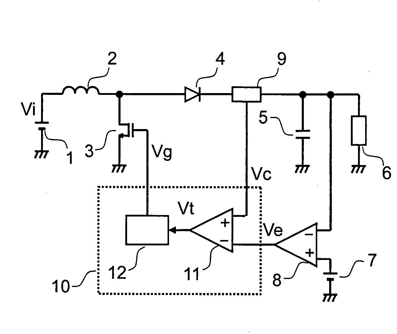
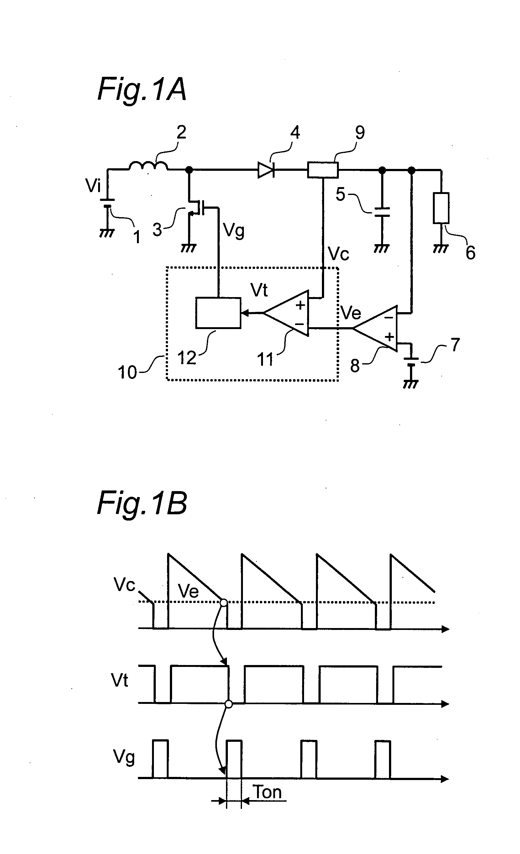
[0037]The step-up converter according to a first embodiment of the present invention will be described below referring to the drawings. FIG. 1A is a circuit diagram showing the step-up converter according to the first embodiment of the present invention, and FIG. 1B is a graph showing the waveforms of the operation thereof.

[0038]Referring to FIG. 1A, numeral 1 designates an input DC power supply, such as a battery, for supplying an input DC voltage Vi. Numeral 2 designates an inductor, one terminal of which is connected to the input DC power supply 1. It is assumed that the inductance of the inductor 2 is L. Numeral 3 designates a main switch that is connected to the other terminal of the inductor 2 and is turned ON / OFF using a drive signal Vg. Numeral 4 designates a rectifier, one terminal of which is connected to the connection point of the inductor 2 and the main switch 3. Numeral 5 designates an output capacitor serving as a smoothing means that is connected to the other termina...

second embodiment

[0051]FIG. 3A is a circuit diagram showing the timer circuit 12a of a step-up converter according to a second embodiment of the present invention. The timer circuit 12a according to the second embodiment can set the minimum OFF time in addition to the ON time setting function of the timer circuit 12 according to the first embodiment described above. Since the configuration of the step-up converter according to the second embodiment is similar to the configuration of the step-up converter according to the first embodiment described above except for the timer circuit 12a, in FIG. 3A, the input DC power supply 1, the inductor 2, the main switch 3, the rectifier 4, the smoothing means 5, the load 6, the reference voltage supply 7, the error amplifier 8 and the current detector 9 shown in FIG. 1A are not shown. In addition, the comparator 11 of the constant current 10 is not shown either since its configuration is similar to that according to the first embodiment. In the timer circuit 12...

third embodiment

[0060]FIG. 4A is a circuit diagram showing the timer circuit 12b of a step-up converter according to a third embodiment of the present invention, wherein the ON time can be corrected using input / output DC voltages in addition to the function of the timer circuit 12a according to the second embodiment described above. Referring to FIG. 4A, the same components as those of the timer circuit 12a of the step-up converter according to the second embodiment shown in FIG. 3A are designated by the same numerals, and their descriptions are omitted. The timer circuit 12b of the step-up converter according to the third embodiment differs from the timer circuit 12a shown in FIG. 3A in the configurations of the current supply circuit 102b and the voltage supply circuit 104b thereof. The circuit configuration of the current supply circuit 102b is shown in FIG. 4B, and the circuit configuration of the voltage supply circuit 104b is shown in FIG. 4C.

[0061]Referring to FIG. 4B, the current supply cir...


PUM


Abstract

The present invention provides a current-mode control step-up converter capable of reducing the minimum duty ratio to a sufficiently small value and facilitating the setting of the maximum duty ratio. The step-up converter comprises a current detector 9 for generating a current detection signal Vc corresponding to the current of a rectifier 4; an error amplifier 8 for generating an error signal Ve corresponding to an output DC voltage Vo; and a control circuit 10 for turning ON / OFF the main switch 3 on the basis of the current detection signal Vc and the error signal Ve. The control circuit 10 comprises a comparator 11 and a timer circuit 12. With this configuration, the ON time of the main switch 3 is set at a predetermined value, and the valley value of an inductor current changing in a triangular waveform is controlled. Hence, the OFF time of the main switch is adjusted to stabilize the output. Since the ON time of the main switch 3 can be set as desired, the minimum duty ratio can be reduced to zero or a sufficiently small value.

Description

BACKGROUND OF THE INVENTION[0001]The present invention relates to a current-mode control step-up converter.[0002]Electronic apparatuses, such as portable apparatuses, use a battery as a power supply. The voltage of this battery is stepped up to a desired voltage using a step-up converter and is used as a power supply voltage for various electronic circuits. The step-up converter is a switching DC-DC converter comprising an inductor, a main switch and a rectifier. The current-mode control system being excellent in stability is known as a control system for the converter. FIG. 10 is a circuit diagram showing the current-mode control step-up converter disclosed in FIG. 4 of Japanese Patent Application Laid-open No. 2000-134923.[0003]The conventional step-up converter shown in FIG. 10 comprises an input DC power supply 201 for supplying an input DC voltage Vi; an inductor 202 and a main switch 203 connected in series with each other and further connected in parallel with the input DC po...

Claims


Application Information

Patent Timeline
IPC IPC(8): G05F1/565
CPCH02M3/156
Inventor ISHII, TAKUYAMOTOMORI, MIKIOMORITA, JUNICHIRYU, TAKASHIKOTO, MASAAKIISHIMARU, MAKOTOKIMURA, KAZUHITOWADA, SATOSHI
Owner PANASONIC SEMICON SOLUTIONS CO LTD
Why Eureka
Try Eureka