
Image processing method, program, storage medium, and apparatus for executing a quantization process of image data by error diffusion

a quantization process and image data technology, applied in the field of image processing methods, program, storage media, image processing apparatus, can solve the problems of difficult to remove adversely affecting the visual impression of reproduced images, and methods that require complicated arithmetic operations and discrimination circuits. , to achieve the effect of simple circuit and removal of image quality deterioration factors

Inactive Publication Date: 2010-03-02
CANON KK
View PDF35 Cites 8 Cited by
  • Summary
  • Abstract
  • Description
  • Claims
  • Application Information

AI Technical Summary

Benefits of technology

[0009]The present invention relates to an image processing technique for removing image quality deterioration factors due to “sweeping”, “texture”, “pseudo contour”, “worm”, and the like in error diffusion by a relatively simple circuit.

Problems solved by technology

With these phenomena, when a multi-valued image is quantized using error diffusion, density reproducibility often impairs.
Such phenomena often adversely influence the visual impression of a reproduced image.
However, the first method requires complicated arithmetic operations and discrimination circuits, look-up tables, or the like.
Also, a complicated tuning process is required to set an optimal threshold value so as to obtain high image quality.
Since the second method uses filters based on a human visual system upon calculation of a feature amount, complicated arithmetic operations and discrimination processes are required.
Furthermore, the second method has nearly no effect of solving problems of “sweeping” and “pseudo contour” due to disappearance of a dot pattern.

Method used


Image

  • Image processing method, program, storage medium, and apparatus for executing a quantization process of image data by error diffusion
  • Image processing method, program, storage medium, and apparatus for executing a quantization process of image data by error diffusion
  • Image processing method, program, storage medium, and apparatus for executing a quantization process of image data by error diffusion

Examples


first embodiment

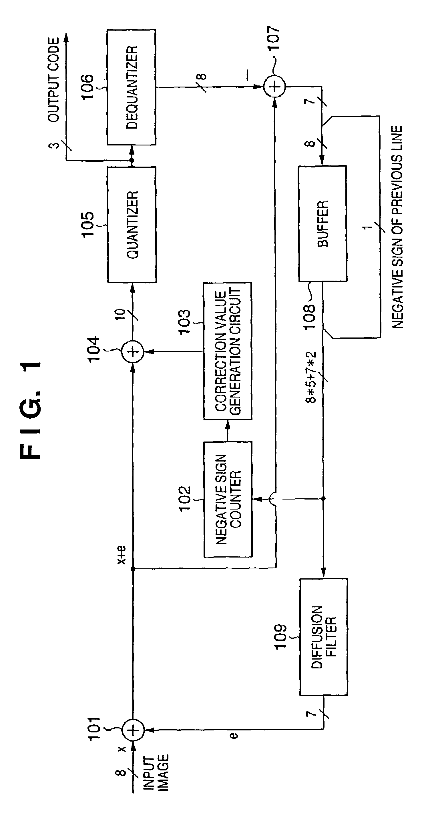
[0031]FIG. 1 is a block diagram showing an example of the arrangement of an image processing apparatus according to the first embodiment of the present invention. Note that the present specification will give an explanation focused on “negative sign (information indicating negative)” of a quantization error in the first embodiment and other embodiments to be described hereinafter. This aims at easy understanding of the present invention. However, the present invention is not limited to information indicating that a quantization error is negative, but may be practiced by replacing it by a positive sign (information indicating positive).

[0032]Referring to FIG. 1, reference numeral 101 denotes an adder which generates image data (first image data) obtained by adding an error amount distributed from a diffusion filter 109. Reference numeral 102 denotes a negative sign counter which extracts and counts negative signs of quantization errors from an error buffer 108. Reference numeral 103 ...

second embodiment

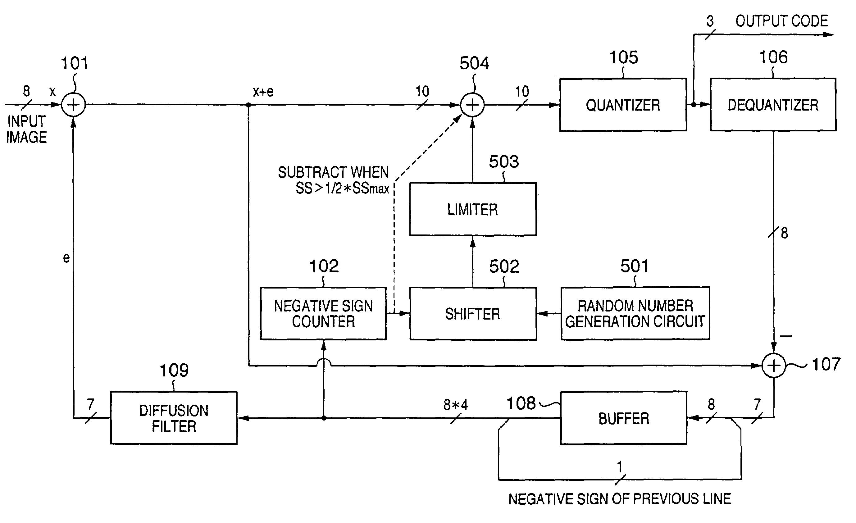
[0071]FIG. 5 is a block diagram showing the arrangement of an image processing apparatus according to the second embodiment of the present invention. Referring to FIG. 5, blocks 101 to 109 have the same functions as those of the corresponding blocks in FIG. 1. In FIG. 5, new blocks 501 to 504 are added, i.e., reference numeral 501 denotes a random number generation circuit; 502, a shifter; 503, a limiter; and 504, an adder / subtractor. Only differences from the first embodiment will be described below with reference to FIG. 17. FIG. 17 is a flowchart showing an example of a correction value generation process corresponding to this embodiment.

[0072]In step S1701, the number SS of negative signs in a pixel group near the pixel of interest is counted by the negative sign counter 102. In step S1702, the random number generation circuit 501 generates a random number of a predetermined number of bits. Furthermore, in step S1703, the shifter 502 determines a shift amount of the random numbe...

third embodiment

[0094]FIG. 14 is a block diagram showing the arrangement of an image processing apparatus according to the third embodiment of the present invention. Referring to FIG. 14, blocks 101 to 109, 501, and 504 have the same functions as those of the corresponding blocks in FIGS. 1 and 5. In FIG. 14, a new block 1401 is added, i.e., reference numeral 1401 denotes a limiter. Only differences from the second embodiment will be described below.

[0095]In this embodiment, a limit table is adopted in place of the shift table used in the second embodiment, and a random number which is limited by a limit value according to the total number SS of negative signs is used as a correction value.

[0096]A practical operation of the present invention corresponding to this embodiment will be described below. The limiter 1401 determines a limit value of the random number with reference to a limit table (to be described in detail later) on the basis of the total number SS of negative signs input from the negat...


PUM


Abstract

An image processing method for executing a quantization process of image data by error diffusion, executes a step of generating first image data by adding a quantization error to input image data, a step of generating second image data by quantizing the first image data by comparing the first image data with a predetermined threshold value, a step of generating third image data by dequantizing the second image data, a calculation step of calculating a quantization error for each pixel on the basis of the difference between the first and third image data, a storage step of storing information indicating a positive / negative sign of the calculated quantization error for a predetermined number of pixels in a storage unit, and a correction value generation step of generating a correction value used to correct at least one of the first image data and the threshold value on the basis of the information which is stored in the storage unit and indicates the positive / negative sign.

Description

FIELD OF THE INVENTION[0001]The present invention relates to an image processing method, program, storage medium, and image processing apparatus and, more particularly, to an image processing method, program, storage medium, and image processing apparatus, which quantize input data into binary or multi-valued data while preserving the difference between the input and output image densities or the like by, e.g., error diffusion.BACKGROUND OF THE INVENTION[0002]Conventionally, an image processing apparatus which converts input multi-grayscale image data into binary image data and outputs the binary image data adopts, e.g., error diffusion as a method of converting a multi-grayscale image into a binary image. With this error diffusion, a quantization error between the grayscale value of a pixel of interest, and a fixed binarization threshold value used to binarize this grayscale value is diffused to the grayscale values of neighboring pixels of the pixel of interest, and these grayscal...

Claims


Application Information

Patent Timeline
Patent Type & Authority Patents(United States)
IPC IPC(8): G06K9/00G06K9/38H04N1/40G06K9/36H04N1/405
CPCH04N1/4053G06T2200/28
Inventor ISHIKAWA, HISASHI
Owner CANON KK
Learn More