Method of stabilizing unconsolidated formation for sand control

a technology of unconsolidated formation and sand control, which is applied in the direction of separation process, sealing/packing, and wellbore/well accessories. it can solve the problems of reducing the relative permeability of hydrocarbons and thus the hydrocarbon productivity of wells, reducing formation permeability, and reducing the productivity loss associated with condensate buildup

Inactive Publication Date: 2010-03-09
HALLIBURTON ENERGY SERVICES INC
View PDF685 Cites 60 Cited by
  • Summary
  • Abstract
  • Description
  • Claims
  • Application Information

AI Technical Summary

Problems solved by technology

This condensate accumulation, sometimes called condensate blocking, reduces the hydrocarbon relative permeability and thus the well's hydrocarbon productivity.
In addition, the presence of aqueous liquids such as this condensate will cause the water swellable clays present in the formation to swell, which further reduces the formation's permeability.
The productivity loss associated with condensate buildup can be substantial.
The pockets of treatment fluid, which are interlocked with hydrocarbon, are hard to remove from the formation without some kind of stimulation treatment.
The high velocity in the porous medium near the wellbore is sometimes sufficient to mobilize fines that can then plug channels in the formation.
More often, formation sand and fines often become unstable and migrate as a result of water movement through the formation.
The presence of a mobile water phase can cause fines migration and subsequent formation damage.
Unconsolidated subterranean zones include those that contain loose particulates and those wherein the bonded particulates have insufficient bond strength to withstand the forces produced by the production of fluids through the zones.
It is however, impossible to eliminate all voids between the screen and the wellbore wall.
Fines fill these voids blocking flow and in some instances fines flowing through these voids erode the screen destroying its effectiveness.
Gravel packs may be time consuming and expensive to install.
Due to the time and expense needed it is sometimes desirable to place a screen without the gravel and, particularly in cases in which an expandable screen is being placed, it may be unrealistic to place a bed of gravel between the expandable screen and the well bore.
Even in circumstances in which it is practical to place a screen without a gravel pack, it is often difficult to determine an appropriate screen size to use as formation sands tend to have a wide distribution of sand grain sizes.
When small quantities of sand are allowed to flow through a screen, screen erosion becomes a significant concern.
However, the ability to provide universal screen mesh that can handle wide particle size distribution of formation sand is unrealistic, if not impossible.
Such resin application may be problematic when, for example, an insufficient amount of spacer fluid is used between the application of the resin and the application of the external catalyst.
When resin is contacted with an external catalyst, an exothermic reaction occurs that may result in rapid polymerization, potentially damaging the formation by plugging the pore channels, halting pumping when the well bore is plugged with solid material, or resulting in a downhole explosion as a result of the heat of polymerization.
Also, these conventional processes are not practical to treat long intervals of unconsolidated regions due to the difficulty in determining whether the entire interval has been successfully treated with both the resin and the external catalyst.
While these unconsolidated formation treatment methods provide improved fines control, multiple treatment steps that are time consuming and expensive are required.

Method used


Image

  • Method of stabilizing unconsolidated formation for sand control
  • Method of stabilizing unconsolidated formation for sand control
  • Method of stabilizing unconsolidated formation for sand control

Examples


example 1

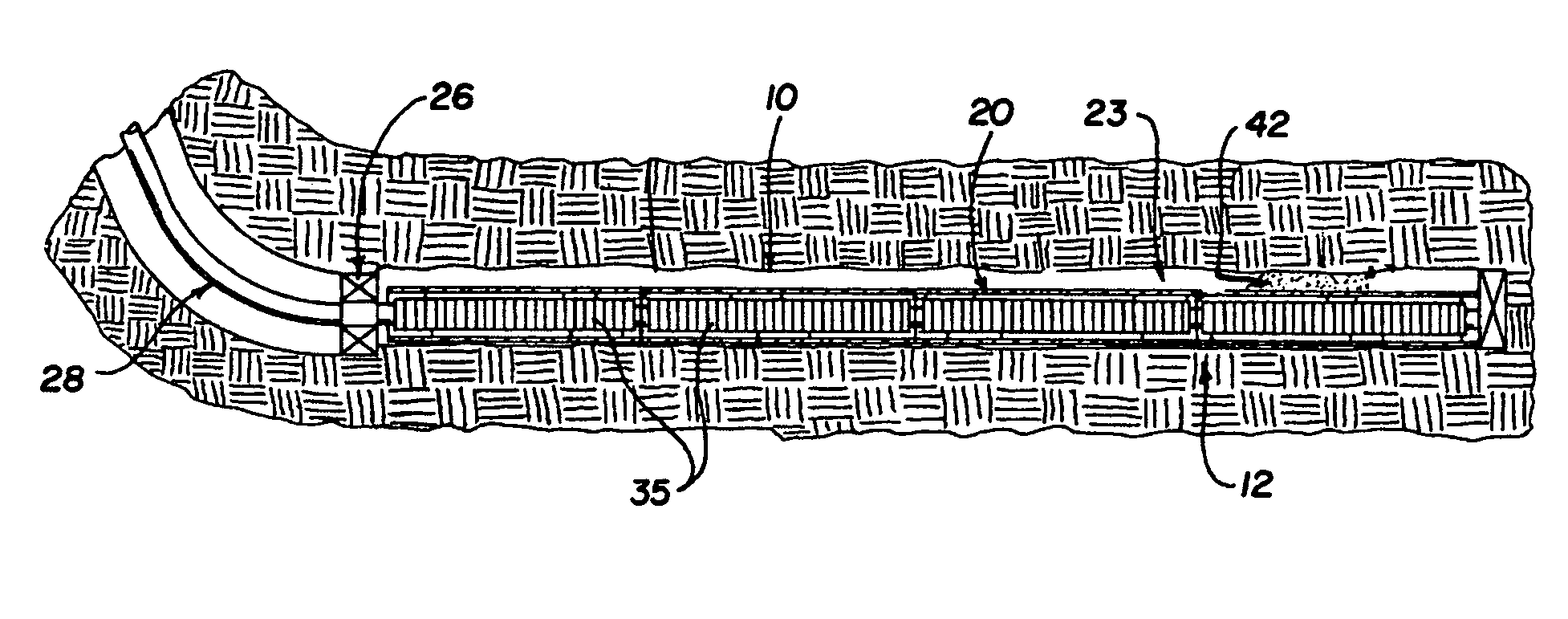
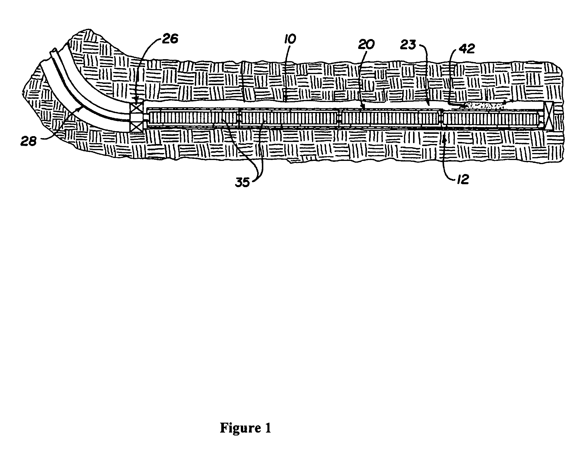
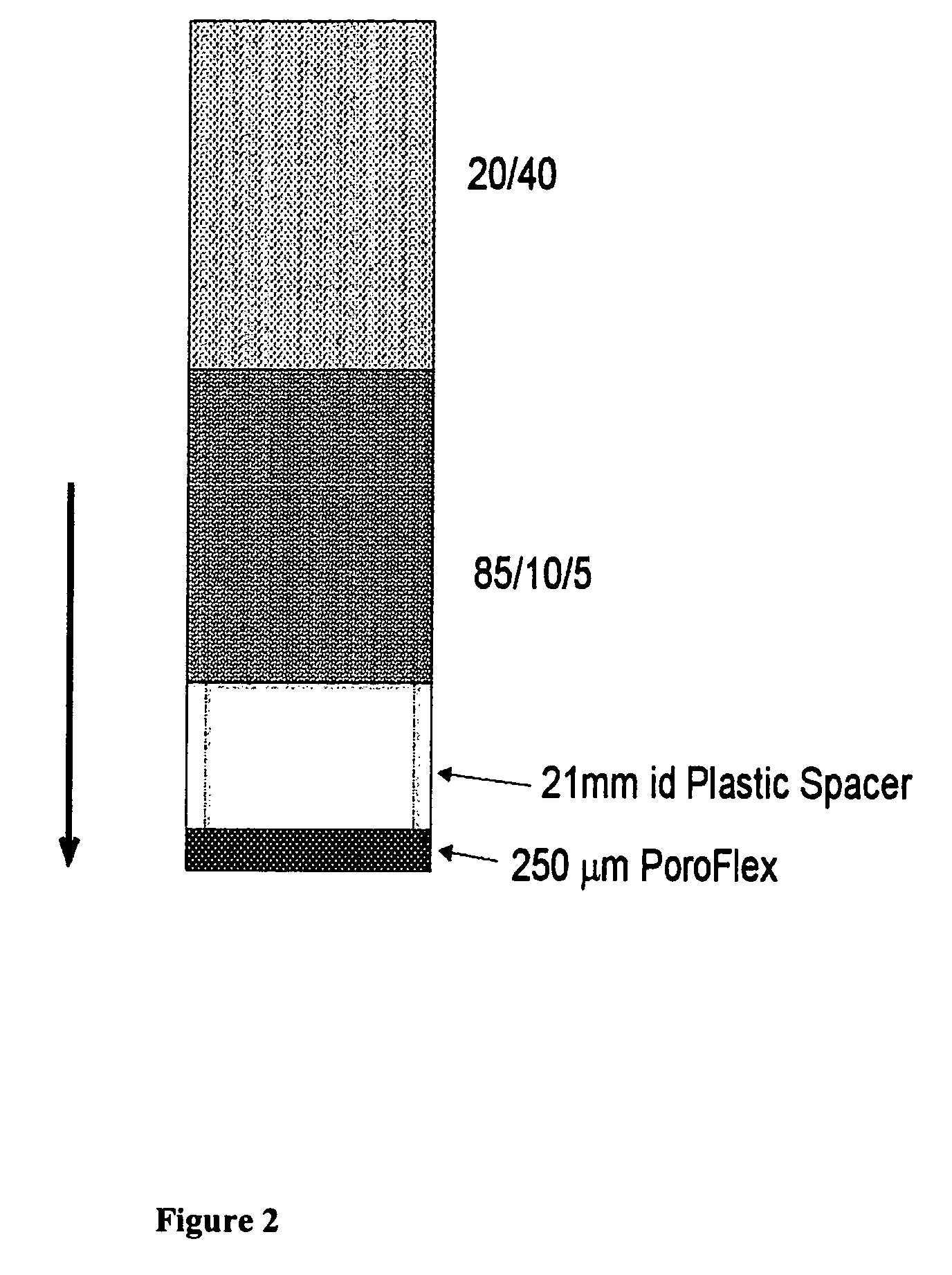
[0067]Experiments were performed with simulated unconsolidated formation and a screen to determine if the methods of the present inventions will result in increased flow through a well screen filter. Sample test sleeves were used to test simulated well conditions. The sleeves were made of transparent material. The sleeves were assembled with well screens across one end to simulate well screens installed in unconsolidated sand formations. For the purposes of these examples, the screen was formed from sections of material used in the Halliburton PoroFlex brand commercial screens. An 85 / 10 / 5 synthetic sand (85% by weight of Oklahoma No. 1 sand, 10% by weight silica flour, and 5% by weight smectite) was packed in the sleeves, followed by 20 / 40 mesh sand. The sands were packed into individual flow cells. In one test setup, a gap was provided behind the PoroFlex (screen piece), for example with a plastic spacer, simulating incomplete compliance of the screen with respect to the formation ...

example 2

[0072]Testing was repeated for both treated and untreated formation sand, except the screen piece was placed tightly against the formation sand simulating complete compliance. Similar results were obtained.

example 3

[0073]In a separate tests using the same set up as described above, fresh distilled water (“DI”) water was injected through treated and untreated samples of formation sand spaced apart from the screen to represent a lack of conformity of the screen to the formation sand. FIG. 4 shows that at flow rate of 5 mL / minute, the pressure drop across the untreated formation sand increased significantly higher than pressure drop across the treated formation sand, which remained low and flat. The flow of DI water through the untreated sand pack was stopped after 15 minutes of flow time. See FIG. 4, “untreated” and “treated” graphed lines showing pressure drop (in pounds per square inch) vs. time (in seconds). This indicated that without the treatment of ultra-thin curable resin, the clay swelled and choked off the permeability. Coating of a thin film as a result of resin treatment helped encapsulate the clay particulates and prevented them from swelling.


PUM

PropertyMeasurementUnit
angleaaaaaaaaaa
cure temperatureaaaaaaaaaa
temperaturesaaaaaaaaaa

Abstract

The invention provides a method for treating a subterranean formation penetrated by a wellbore. The method comprises the steps of: (a) introducing a composition through the wellbore into the subterranean formation, wherein the composition comprises: (i) a solvent consisting essentially of an aqueous dissolvable solvent comprising any solvent that is at least 25% by weight soluble in water, wherein the solvent is from about 90% to about 99.9% by weight of the composition; and (ii) a curable resin, wherein the curable resin is from about 0.01% to about 10% by weight of the composition; wherein the curable resin and the solvent are mutually selected such that, for the ratio of the curable resin to the solvent, the curable resin is soluble in the solvent; and (b) installing a mechanical sand control device into the wellbore either before or after introducing the composition into the wellbore.

Description

CROSS-REFERENCE TO RELATED APPLICATIONS[0001]This is a continuation-in-part of application entitled “METHODS FOR CONTROLLING MIGRATION OF PARTICULATES IN A SUBTERRANEAN FORMATION,” Ser. No. 11 / 092,210, filed Mar. 29, 2005 now U.S. Pat. No. 7,448,451.STATEMENT REGARDING FEDERALLY SPONSORED RESEARCH OR DEVELOPMENT[0002]Not Applicable.REFERENCE TO A MICROFICHE APPENDIX[0003]Not applicable.TECHNICAL FIELD[0004]The invention generally relates to compositions and methods for treating a subterranean formation. More specifically, the invention relates to compositions and methods for use in treating a subterranean formation for controlling the migration of particulates, such as formation sand and fines.BACKGROUND[0005]Hydrocarbon is obtained from a subterranean formation by drilling a wellbore that penetrates the hydrocarbon-bearing formation. It is desirable to maximize both the rate of flow and the overall amount of flow of hydrocarbon from the subterranean formation to the surface.[0006]T...

Claims


Application Information

Patent Timeline
Patent Type & Authority Patents(United States)
IPC IPC(8): E21B33/138E21B43/26E21B43/27
CPCC09K8/5083C09K8/5086C09K8/56C09K8/575C09K8/5753C09K8/5755C09K8/62C09K8/72
Inventor NGUYEN, PHILIP D.RICKMAN, RICHARD D.DUSTERHOFT, RONALD G.
Owner HALLIBURTON ENERGY SERVICES INC
Why Eureka
Try Eureka