Carrier assembly for percussion instruments

a technology for percussion instruments and carriers, applied in the direction of instruments, natural mineral layered products, music aids, etc., can solve the problems of no assembly, prior art does not disclose assembly, etc., and achieve the effect of convenient transportation, carrying and storag

Inactive Publication Date: 2010-03-09
RANDALL MAY INT
View PDF28 Cites 24 Cited by
  • Summary
  • Abstract
  • Description
  • Claims
  • Application Information

AI Technical Summary

Benefits of technology

[0021]Another object of the invention is to provide an instrument carrier that can be folded to allow for easier transportation, carrying and storage.

Problems solved by technology

The prior art discloses many examples of apparatus for supporting percussion instruments but none provide the combination of features that allow for a lockable hinge clamp that allows the carrier to both articulate, fold and lock into position.
The prior art does not disclose an assembly that can be folded to allow for easier transportation and storage.

Method used


Image

  • Carrier assembly for percussion instruments
  • Carrier assembly for percussion instruments
  • Carrier assembly for percussion instruments

Examples


Embodiment Construction

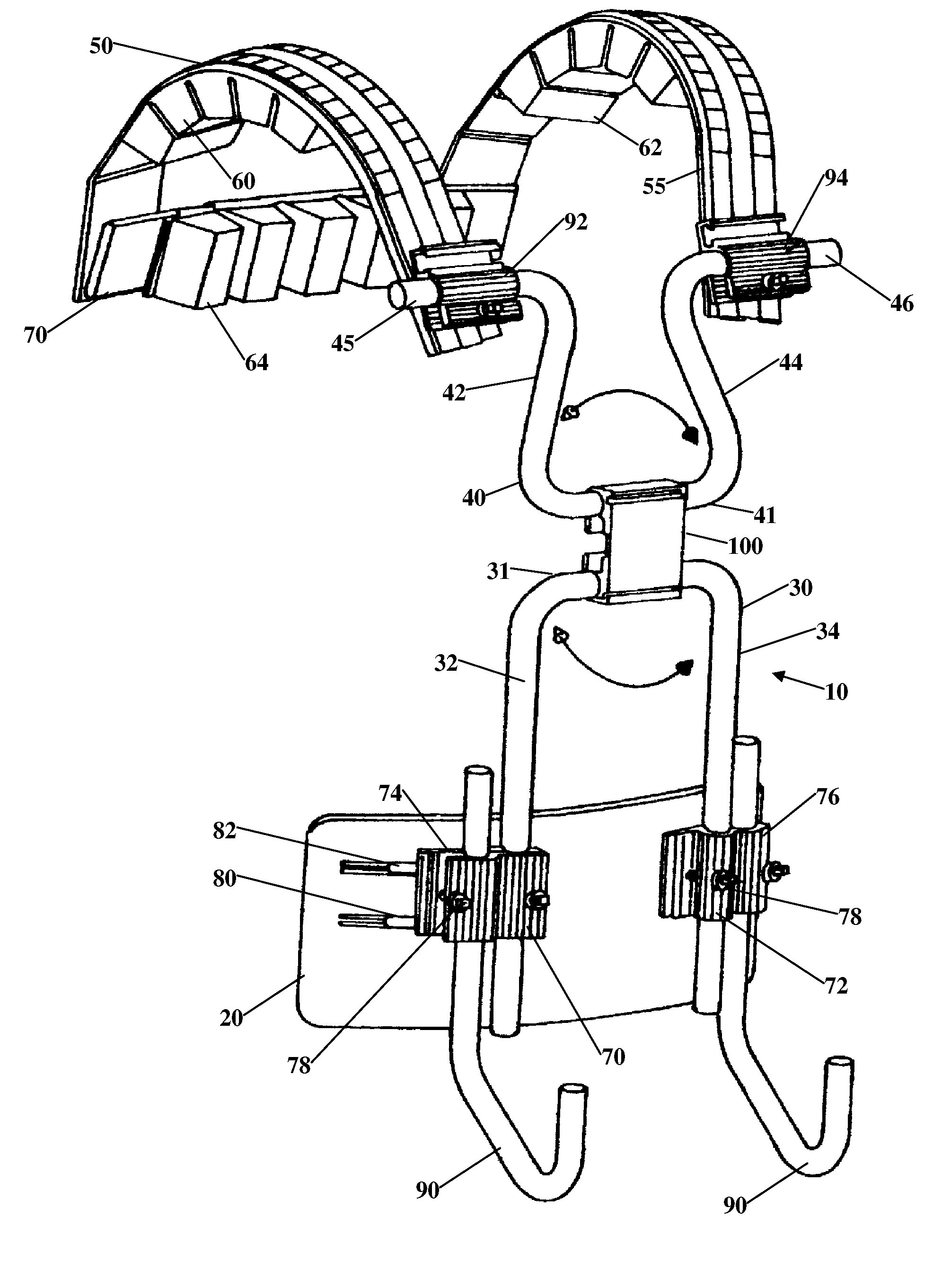
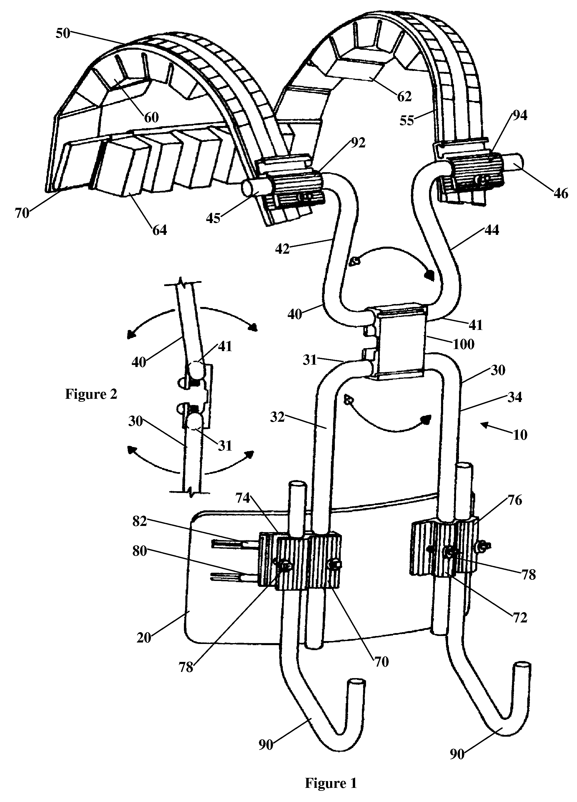
[0041]Referring to FIG. 1, there is shown a tubular T-bar-type carrier 10 for percussion instruments that comprises a belly plate 20, lower and upper vertical supporting rods or tubes 30 and 40. Lower rod or tube 30 is U-shaped lower component with parallel portions 32 and 34 supporting belly plate 20. Upper rod or tube 40 is U-shaped chest component with legs 42 and 44 having out-turned portions 45 and 46 connected to shoulder supporting rigid shoulder straps 50 and 55 and back bar 70. Back bar 70 may be removably secured to shoulder straps 50 and 55 or may be fixed as by welding or the like. Shoulder straps 50, 55, and back bar 70 have cushions 60, 62 and 64, respectively. The cushions are of a type used to pad the interior of football and other sports helmets and are shown in more detail in co-issued Pat. No. 6,028,257. The cushions have a backing strip of polyvinyl plastic film. A thin sheet of polyvinyl film encloses blocks of closed pore plastic (e.g., polystyrene or polyureth...


PUM

PropertyMeasurementUnit
flexibleaaaaaaaaaa
weightaaaaaaaaaa
pressureaaaaaaaaaa

Abstract

Drum hardware and drum secured thereon are preferably supported on a vest type carrier or a T-bar carrier having a plurality of separate parts removable from each other and formed of a rigid plastic, light metal such as magnesium, aluminum or titanium. The removable hardware includes a removable back support member. The instrument carrier includes an articulating hinge that allows for positive, negative or neutral horizontal positioning of the instruments. The articulating hinge assembly further allows the carrier to be folded for easier transportation and storage in a smaller area.

Description

CROSS REFERENCE TO RELATED APPLICATION[0001]This application is a continuation-in-part of applicant's applications U.S. application Ser. No. 10 / 831,638 filed Apr. 23, 2004, now U.S. Pat. No. 6,881 ,886, issued Apr. 19, 2005 which claims the benefit of Continuation-in-part U.S. application Ser. No. 10 / 374,676 filed Feb. 26, 2003 now U.S. Pat. No. 7,071,401, issued Jul. 4, 2006 ,which claims the benefit of Continuation-in-part of application Ser. No. 10 / 170,005 filed Jun. 10, 2002, now U.S. Pat. No. 6,770,805, issued Aug. 3, 2004, which claims the benefit of Divisional application U.S. Ser. No. 09 / 756,479 filed Jan. 8, 2001, now U.S. Pat. No. 6,403,869, issued Jul. 11, 2002, which claims the benefit of Continuation-in-part application U.S. Ser. No. 09 / 507,800 filed Feb. 22, 2000, now U.S. Pat. No. 6,172,290, issued Jan. 9, 2001, which claims the benefit of Divisional application U.S. Ser. No. 09 / 497,265 filed Feb 3, 2000, now U.S. Pat. No. 6,323,407, issued Nov. 27, 2001.In a concise ...

Claims


Application Information

Patent Timeline
Patent Type & Authority Patents(United States)
IPC IPC(8): A45F3/10B32B19/04G10D13/02G10D13/24G10G5/00
CPCG10D13/00G10G5/005G10D13/28G10D13/24
Inventor MAY, RANDALL L
Owner RANDALL MAY INT
Why Eureka
Try Eureka