Micro-fluid ejection devices, methods for making micro-fluid ejection heads, and micro-fluid ejection head having high resistance thin film heaters

a technology of micro-fluid ejection and ejection head, which is applied in the direction of metal-working equipment, printing, writing implements, etc., can solve the problems of increasing complexity, ejection head, which is the primary component of micro-fluid devices, and continues to evolve and become more complex, so as to reduce parasitic resistance, reduce energy requirements, and increase resistance

Inactive Publication Date: 2010-03-09
LEXMARK INT INC +1
View PDF7 Cites 1 Cited by
  • Summary
  • Abstract
  • Description
  • Claims
  • Application Information

AI Technical Summary

Benefits of technology

[0002]Micro-fluid ejection devices such as ink jet printers continue to experience wide acceptance as economical replacements for laser printers. Micro-fluid ejection devices also are finding wide application in other fields such as in the medical, chemical, and mechanical fields. As the capabilities of micro-fluid ejection devices are increased to provide higher ejection rates, the ejection heads, which are the primary components of micro-fluid devices, continue to evolve and become more complex.
[0006]An advantage of the exemplary embodiments is that they may provide improved micro-fluid ejection heads having thermal ejection heaters that have lower energy requirements and less sensitivity to parasitic resistance. The heater resistors described herein may also have increased resistance which, for example, enables the resistors to be driven with smaller drive transistors, thereby reducing the substrate area required for active devices to drive the heater resistors. A reduction in the area required for active devices to drive the heaters enables the use of a smaller substrate, thereby reducing the cost of the ejection heads.

Problems solved by technology

As the capabilities of micro-fluid ejection devices are increased to provide higher ejection rates, the ejection heads, which are the primary components of micro-fluid devices, continue to evolve and become more complex.

Method used


Image

  • Micro-fluid ejection devices, methods for making micro-fluid ejection heads, and micro-fluid ejection head having high resistance thin film heaters
  • Micro-fluid ejection devices, methods for making micro-fluid ejection heads, and micro-fluid ejection head having high resistance thin film heaters
  • Micro-fluid ejection devices, methods for making micro-fluid ejection heads, and micro-fluid ejection head having high resistance thin film heaters

Examples


Embodiment Construction

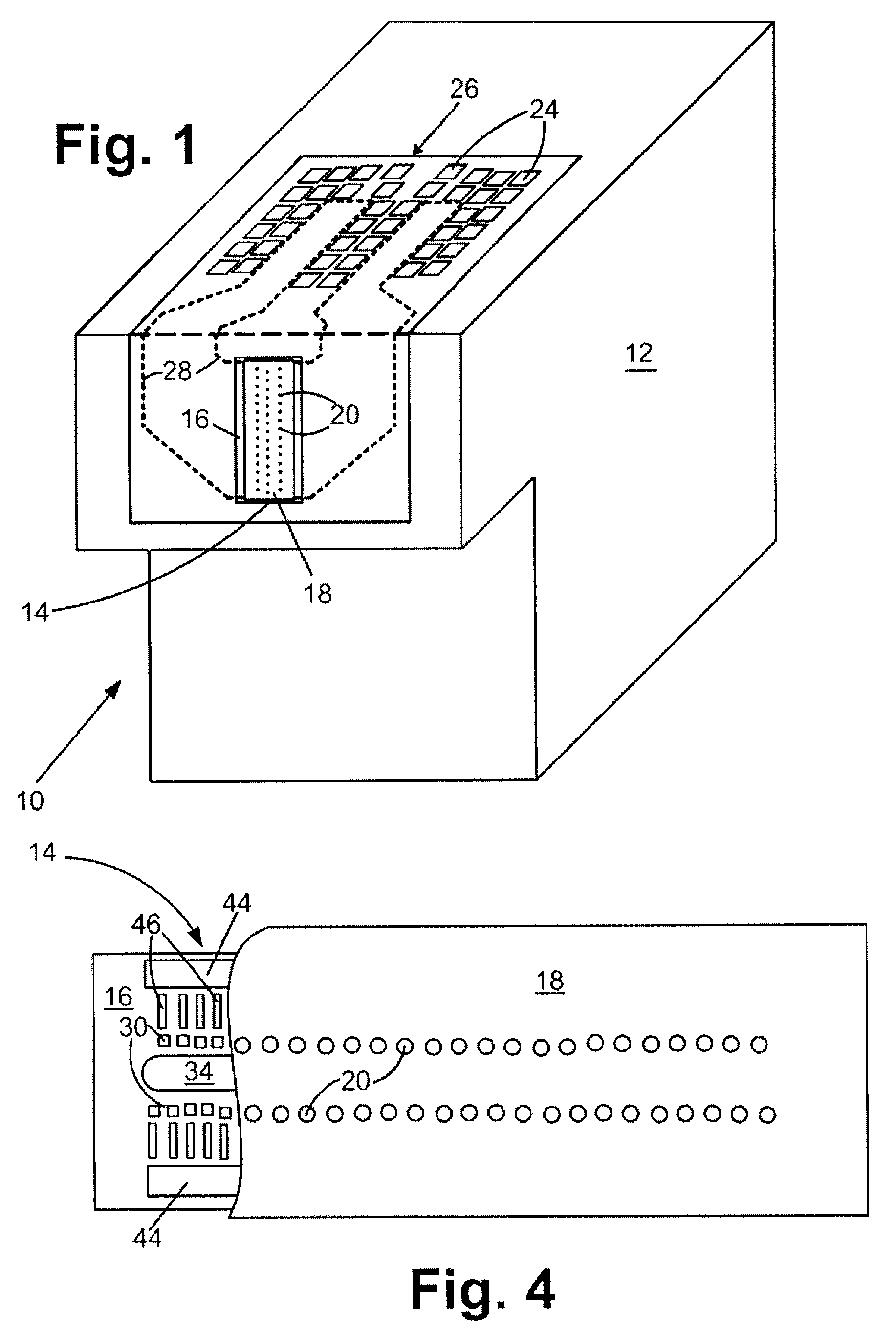
[0015]With reference to FIG. 1, a fluid cartridge 10 for a micro-fluid ejection device is illustrated. The cartridge 10 includes a cartridge body 12 for supplying a fluid to a micro-fluid ejection head 14. The fluid may be contained in a storage area in the cartridge body 12 or may be supplied from a remote source to the cartridge body.

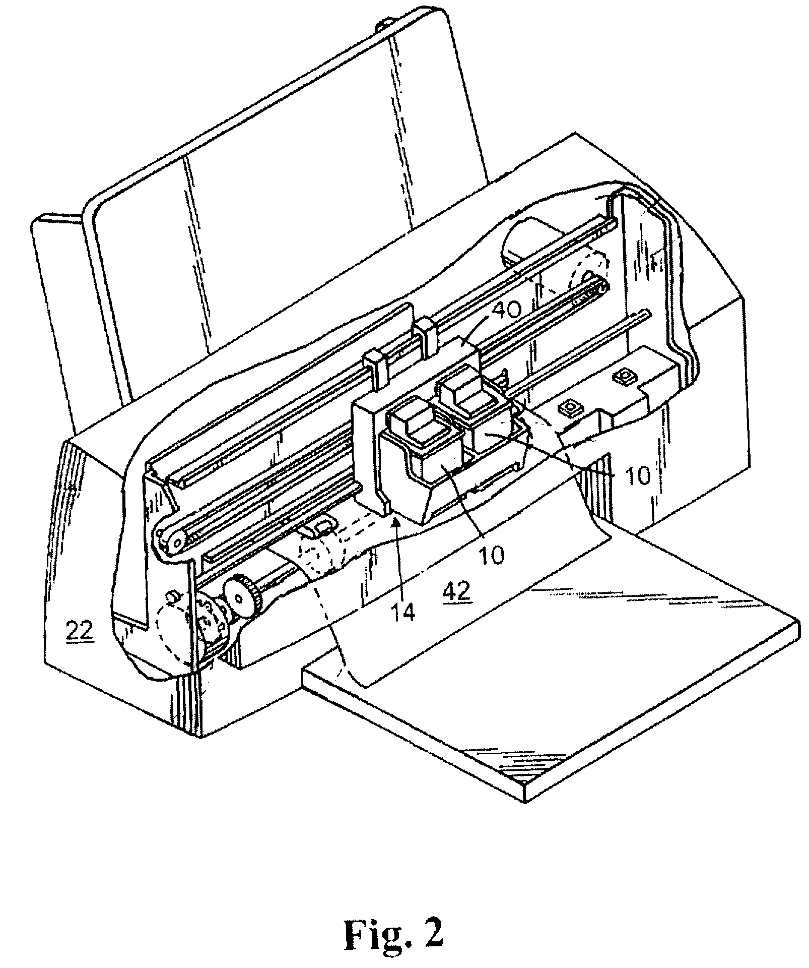
[0016]The exemplary micro-fluid ejection head 14 includes a substrate 16 and a nozzle plate 18 containing nozzles 20. The cartridge 10 may be removably attached to a micro-fluid ejection device such as an ink jet printer 22 (FIG. 2). Accordingly, electrical contacts 24 are provided on a flexible circuit 26 for electrically connecting the cartridge 10 to the micro-fluid ejection device 22. The flexible circuit 26 includes electrical traces 28 that are connected to the substrate 16 of the micro-fluid ejection head 14.

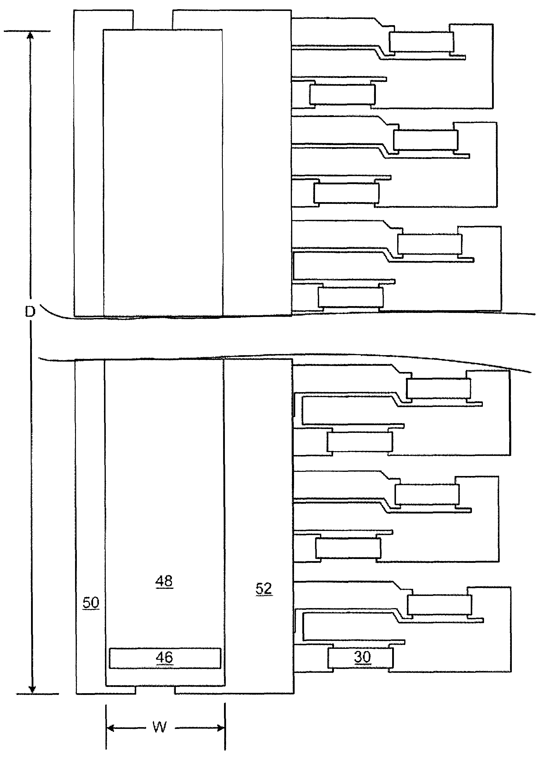
[0017]An enlarged cross-section view, not to scale, of a portion of the micro-fluid ejection head 14 is illustrated in FIG. 3. The micro-f...


PUM

PropertyMeasurementUnit
thicknessaaaaaaaaaa
sheet resistanceaaaaaaaaaa
temperatureaaaaaaaaaa

Abstract

Micro-fluid ejection devices, methods for making micro-fluid ejection heads, and micro-fluid ejection heads, including a micro-fluid ejection head. One such micro-fluid ejection head has relatively high resistance thin film heaters adjacent to a substrate. The thin film material comprises silicon, metal, and carbon (SiMC wherein M is a metal). Each thin film heater has a sheet resistance ranging from about 100 to about 600 ohms per square and a thickness ranging from about 100 to about 800 Angstroms.

Description

TECHNICAL FIELD[0001]The disclosure relates to micro-fluid ejection heads and, in a particular exemplary embodiment, to thin film heater resistors having high resistance.BACKGROUND AND SUMMARY[0002]Micro-fluid ejection devices such as ink jet printers continue to experience wide acceptance as economical replacements for laser printers. Micro-fluid ejection devices also are finding wide application in other fields such as in the medical, chemical, and mechanical fields. As the capabilities of micro-fluid ejection devices are increased to provide higher ejection rates, the ejection heads, which are the primary components of micro-fluid devices, continue to evolve and become more complex.[0003]For example, higher resistance heater materials may be required in order to provide relatively large micro-fluid ejection head substrates so as to achieve faster fluid ejection speeds while using lower driving currents and lower nucleation energies. Higher resistance heater materials may also be ...

Claims


Application Information

Patent Timeline
Patent Type & Authority Patents(United States)
IPC IPC(8): B41J2/05
CPCB41J2/14129Y10T29/49401B41J2202/11B41J2202/03
Inventor GUAN, YIMINJACOBSEN, STUARTSULLIVAN, CARL EDMOND
Owner LEXMARK INT INC
Why Eureka
Try Eureka