

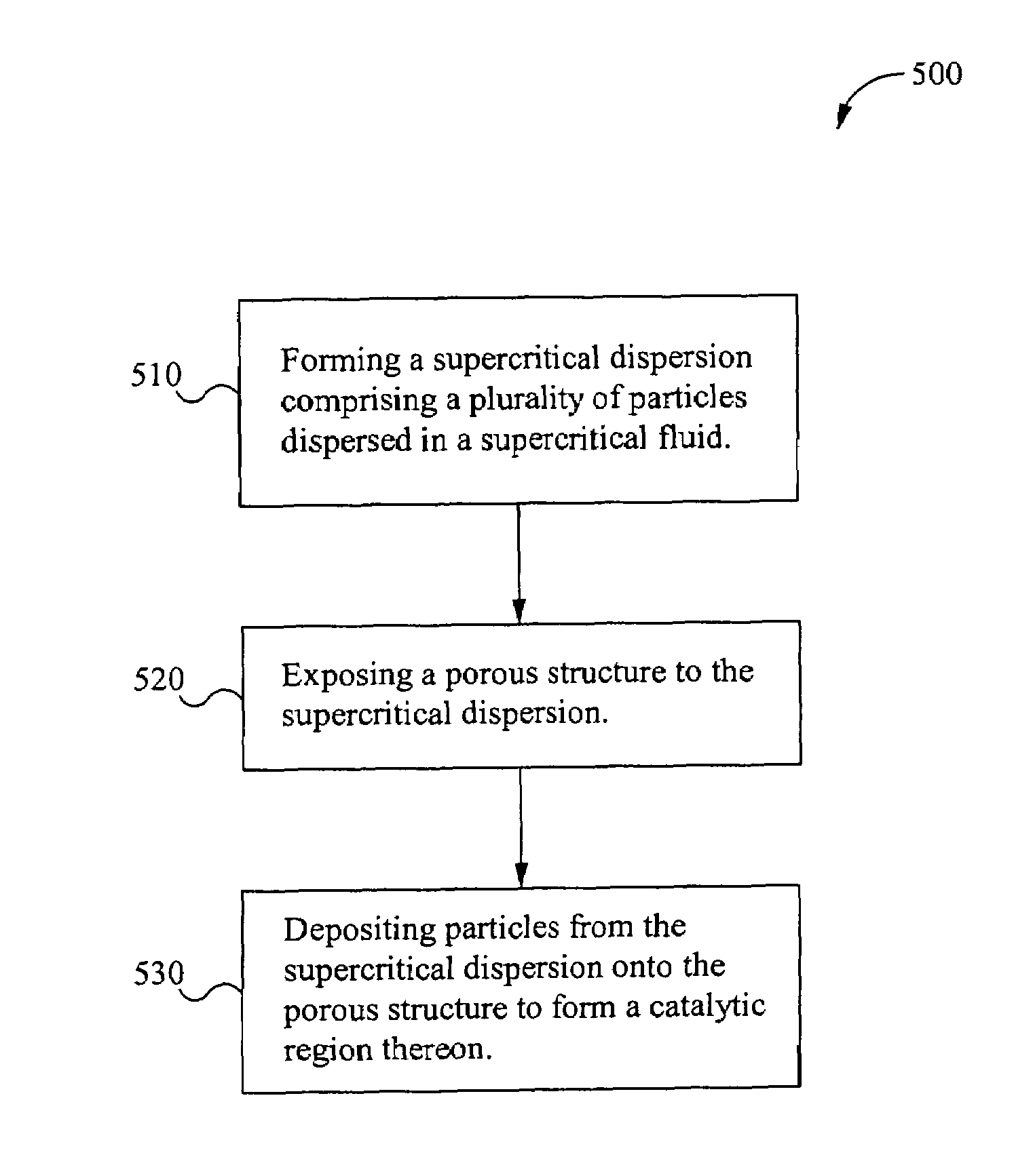
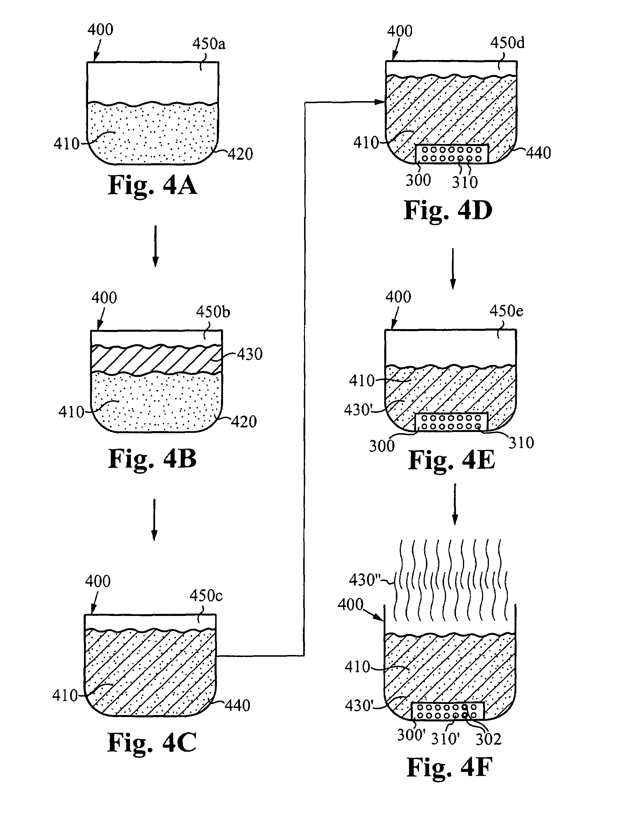
Formation of catalytic regions within porous structures using supercritical phase processing
a technology of supercritical phase and catalytic regions, which is applied in the direction of physical/chemical process catalysts, prosthesis, lighting and heating apparatus, etc., can solve the problems of arbitrary materials not being able to form into a selected microporous structure, sieves, and microporous structures that do not provide chemical catalysis
- Summary
- Abstract
- Description
- Claims
- Application Information
AI Technical Summary
Benefits of technology
Problems solved by technology
Method used
Image

Examples
Embodiment Construction
[0019]The description below concerns several embodiments of the invention. The discussion references the illustrated preferred embodiment. However, the scope of the present invention is not limited to either the illustrated embodiment, nor is it limited to those discussed, to the contrary, the scope should be interpreted as broadly as possible based on the language of the Claims section of this document.
[0020]This disclosure refers to both particles and powders. These two terms are equivalent, except for the caveat that a singular “powder” refers to a collection of particles. The present invention may apply to a wide variety of powders and particles.
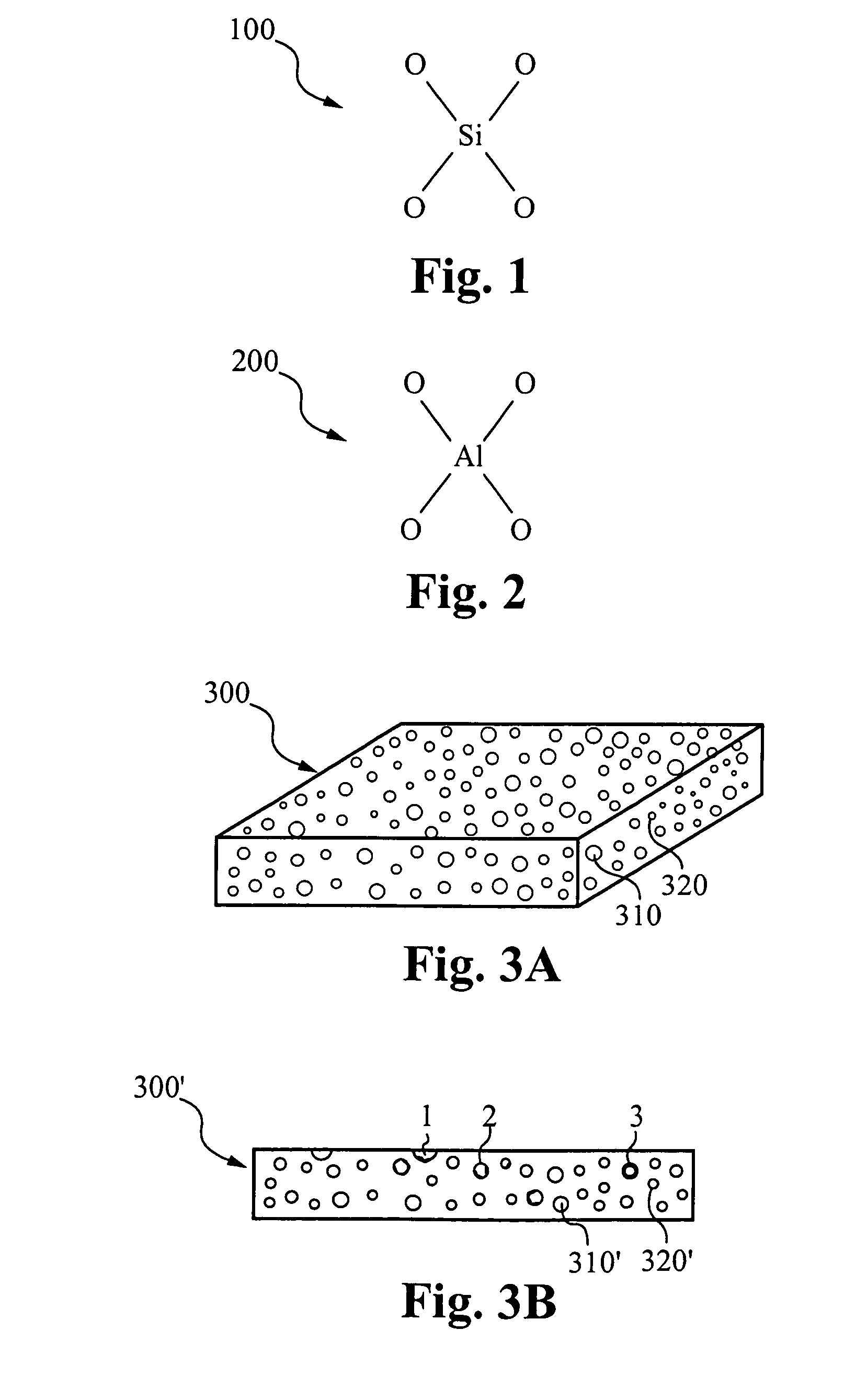
[0021]For the purposes of this disclosure, a microporous structure is a structure having a plurality of very fine pores. In one embodiment, a microporous structure comprises a plurality of pores having an average pore diameter of less than 1 micron. In another embodiment, the microporous structure comprises a plurality of pores having an...
PUM
| Property | Measurement | Unit |
|---|---|---|
| pore diameter | aaaaa | aaaaa |
| pore diameter | aaaaa | aaaaa |
| grain size | aaaaa | aaaaa |
Abstract
Description
Claims
Application Information