Dense plasma focus apparatus

Inactive Publication Date: 2010-03-16
KRISHNAN MAHADEVAN
View PDF33 Cites 50 Cited by
  • Summary
  • Abstract
  • Description
  • Claims
  • Application Information

AI Technical Summary

Benefits of technology

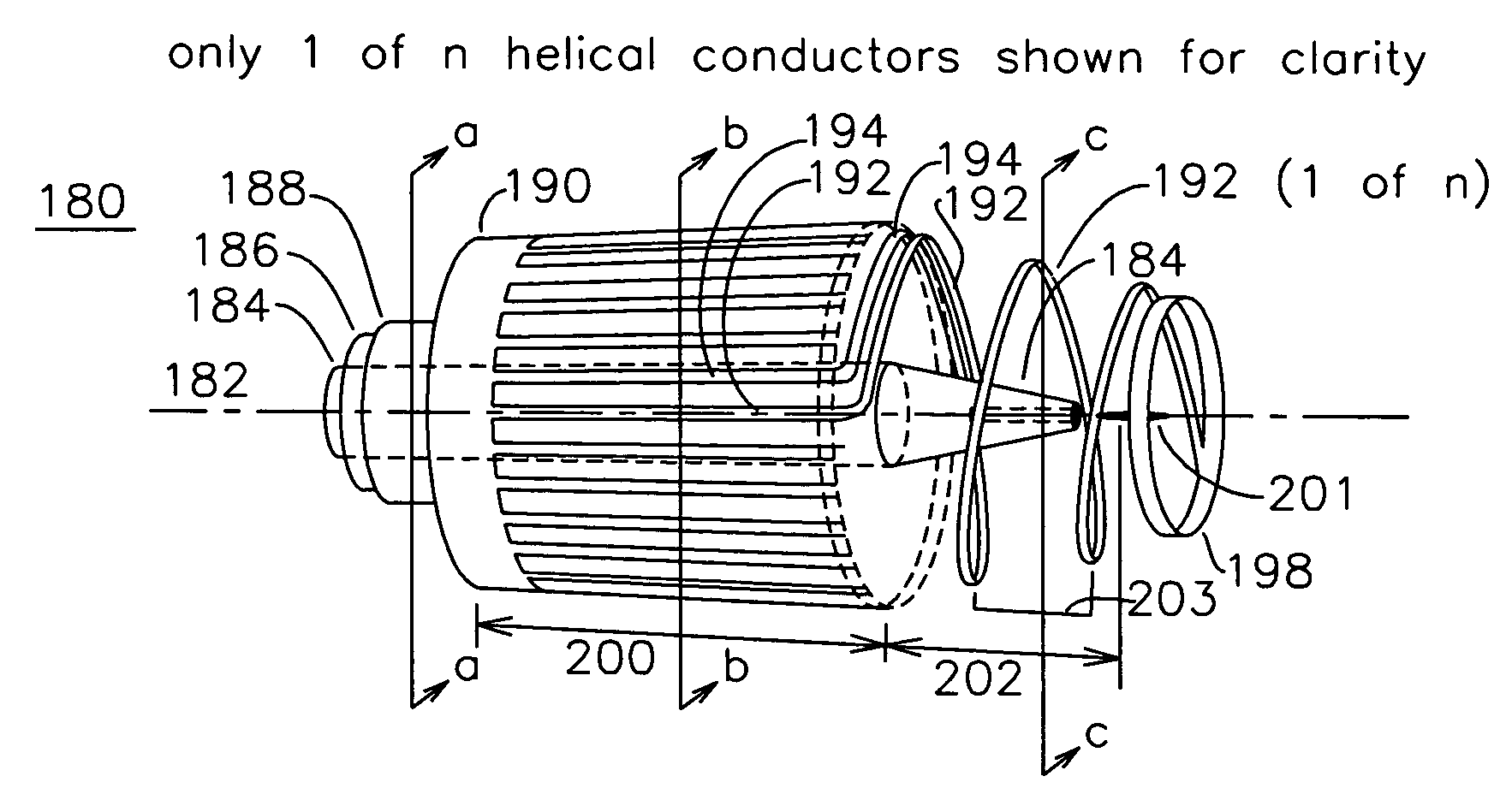
[0018]In a third embodiment, an inner electrode is placed on an axis, the inner electrode having a cylindrical part and a tapered part. The outer electrode is formed from a plurality of conductors which are disposed a fixed distance from the inner electrode and also parallel to the axis, the conductors separated from the inner electrode by a substantially fixed distance over a first acceleration extent where the inner conductor is cylindrical. The outer electrode conductors in the initial axial section need not be mechanically or electrically isolated. In the tapered region of the inner conductor,

Problems solved by technology

The high energy particles (ions) thus generated propagate forward to couple out of the device, while the counter-propagating particles (electrons) can damage the center electrode through excessive heat formation from inelastic collisions with the electrode, and can also result in the generation of undesired secondary debris from the electrode.
The wide conductors reduce the current d

Method used


Image

  • Dense plasma focus apparatus
  • Dense plasma focus apparatus
  • Dense plasma focus apparatus

Examples


Embodiment Construction

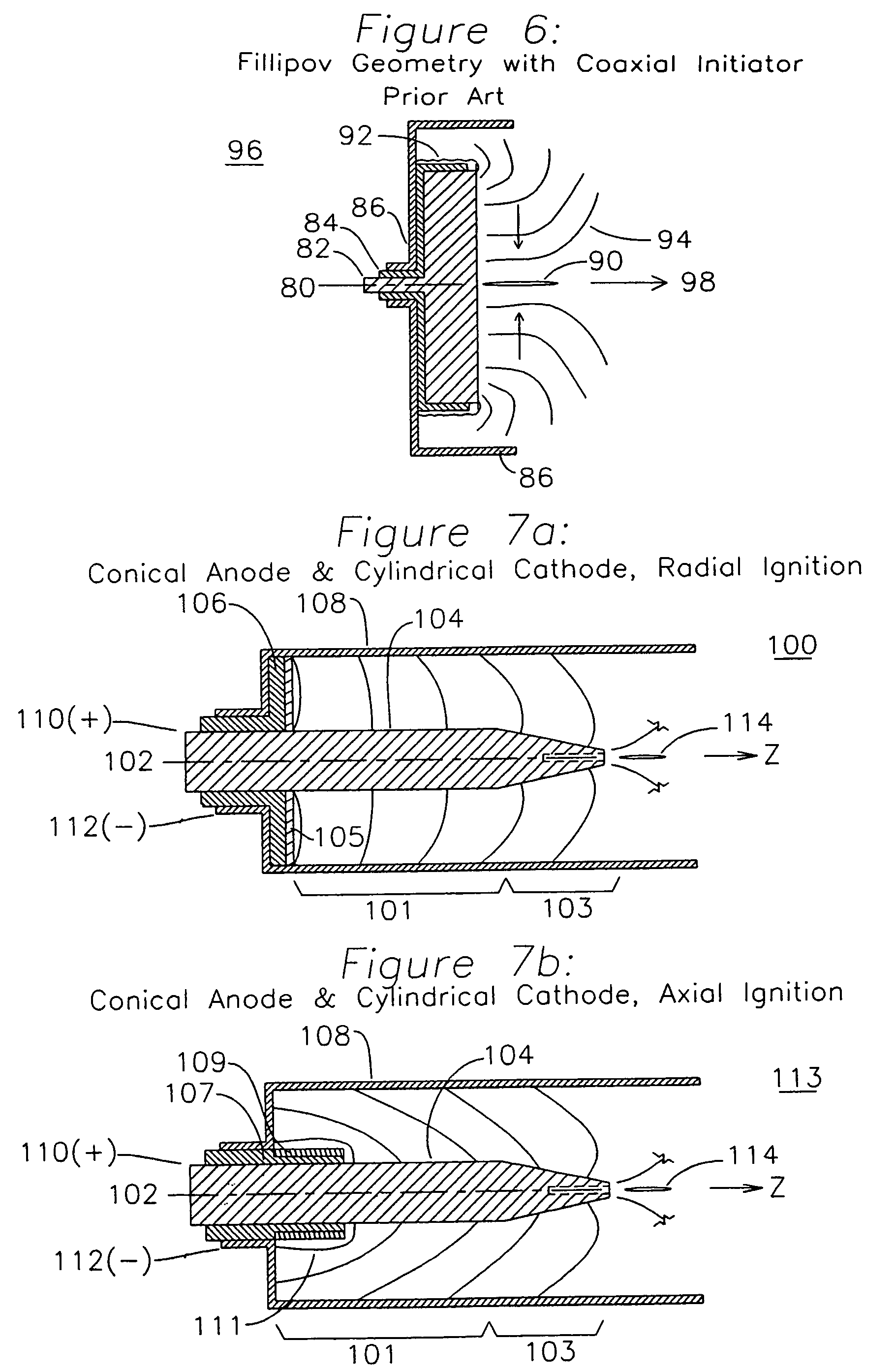
[0033]FIG. 7a shows a dense plasma focus device 100 having an axis 102 and an inner electrode 104 which is cylindrical over a first plasma acceleration extent 101 and tapered over a final plasma acceleration extent 103. The inner electrode 104 is surrounded by a cylindrical outer electrode 108, and is insulated in a plasma initiation end by insulator 106. The insulator 106 serves to ensure the electrical isolation of the inner electrode 104 from the outer electrode 108. On a surface of insulator 106 is a plasma formation surface which is formed from a refractory insulator 105, typically ceramic or glass, which allows the repetitive formation of a high temperature plasma without damaging the underlying insulator 106. After formation of the initial plasma on the surface of the plasma formation disk 105, the plasma expands into an azimuthally continuous radial sheet from the inner electrode 104 to the outer electrode 108. The insulators 105 and 106 also provide a region behind the plas...


PUM

PropertyMeasurementUnit
Lengthaaaaaaaaaa
Lengthaaaaaaaaaa
Lengthaaaaaaaaaa

Abstract

An apparatus for the formation of a dense plasma focus (DPF) has a center electrode formed about an axis, where the center electrode includes a cylindrical part and a tapered part. An outer electrode is formed about the center electrode, and may be either cylindrical, tapered, or formed from a plurality of individual conductors including a helical conductor arrangement surrounding the tapered region of the center conductor. The taper of the center electrode results in an enhanced azimuthal B field in the final region of the device, resulting in increased plasma velocity prior to the dense plasma focus. Using the outer electrode helical structure an auxiliary axial B field is generated during the final acceleration region of the plasma, which reduces axial modal tearing of the plasma in the final acceleration region.

Description

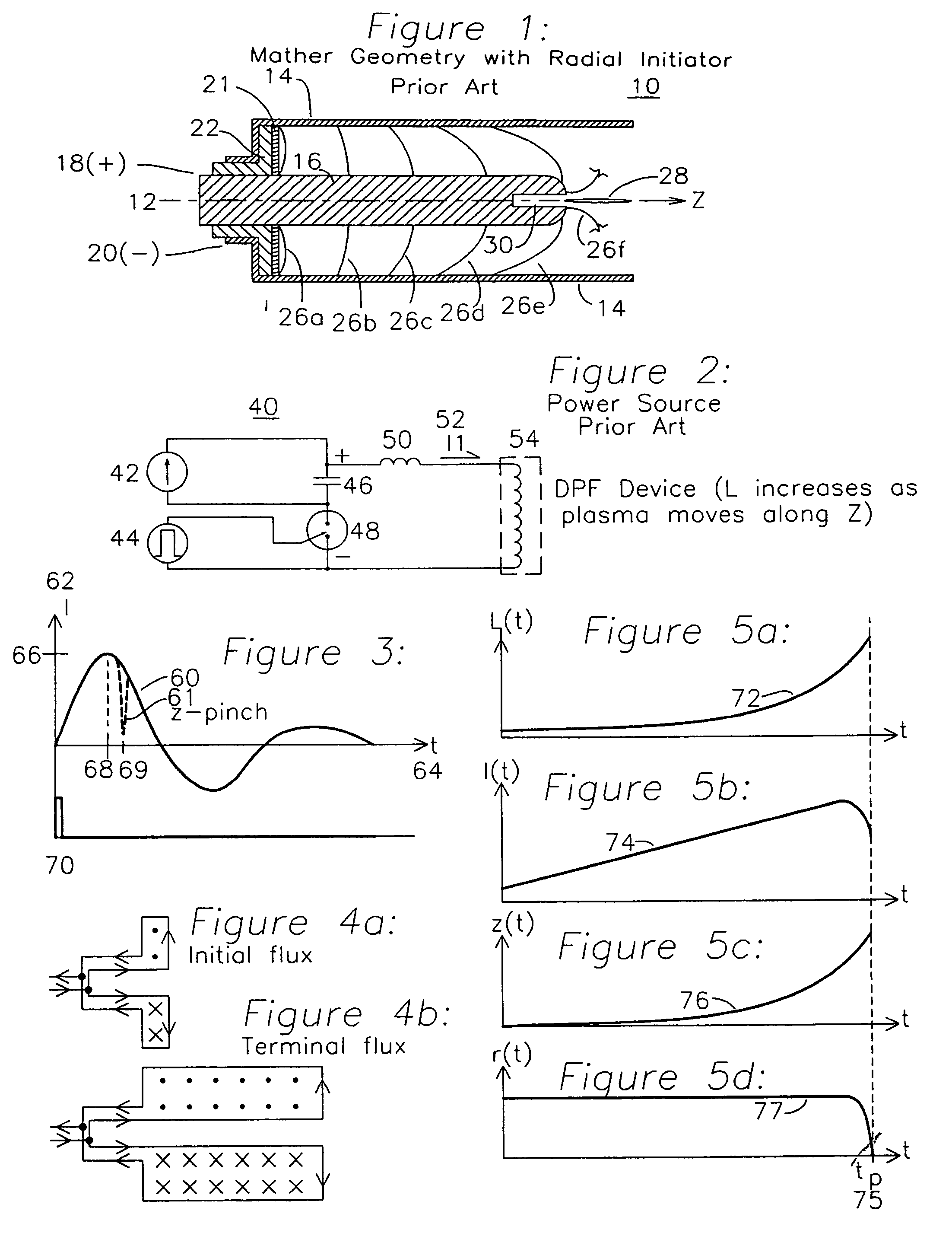
FIELD OF THE INVENTION[0001]The present invention relates to the class of devices which form a plasma and use a self-generated B field to accelerate the plasma towards a pinch zone, thereby forming a dense plasma focus (DPF) which may be used as the source of formation of a variety of particles such as neutrons or x-rays.BACKGROUND OF THE INVENTION[0002]An apparatus for the formation of a dense plasma focus (DPF) was described and characterized in “Characteristics of the Dense Plasma Focus Discharge” by Mather and Bottoms in 1968, one implementation of which is shown in the cross section view of FIG. 1. Independent discovery by Filippov using the geometry of FIG. 6 also occurred in Russia around the same time. The primary difference between the Mather geometry of FIG. 1 and the Filippov geometry of FIG. 6 is the radial to axial geometric aspect ratio and radial vs coaxial plasma initiation. Referring to FIG. 1, a high voltage is applied from a capacitor through a switch to the DPF d...

Claims


Application Information

Patent Timeline
IPC IPC(8): B23K10/00H05H1/24
CPCG21G4/02H05G2/003H05H1/48H05H3/06
Inventor KRISHNAN, MAHADEVANTHOMPSON, JOHN R.
Owner KRISHNAN MAHADEVAN
Why Eureka
Try Eureka