

Dense plasma focus apparatus
a plasma focus and focus device technology, applied in the direction of accelerators, greenhouse gas reduction, plasma techniques, etc., can solve the problems of stray inductance increasing with increasing the frequency of applied potential, reducing the capacity c of capacitors, and not being able to avoid or control
- Summary
- Abstract
- Description
- Claims
- Application Information
AI Technical Summary
Benefits of technology
Problems solved by technology
Method used
Image

Examples
example 1
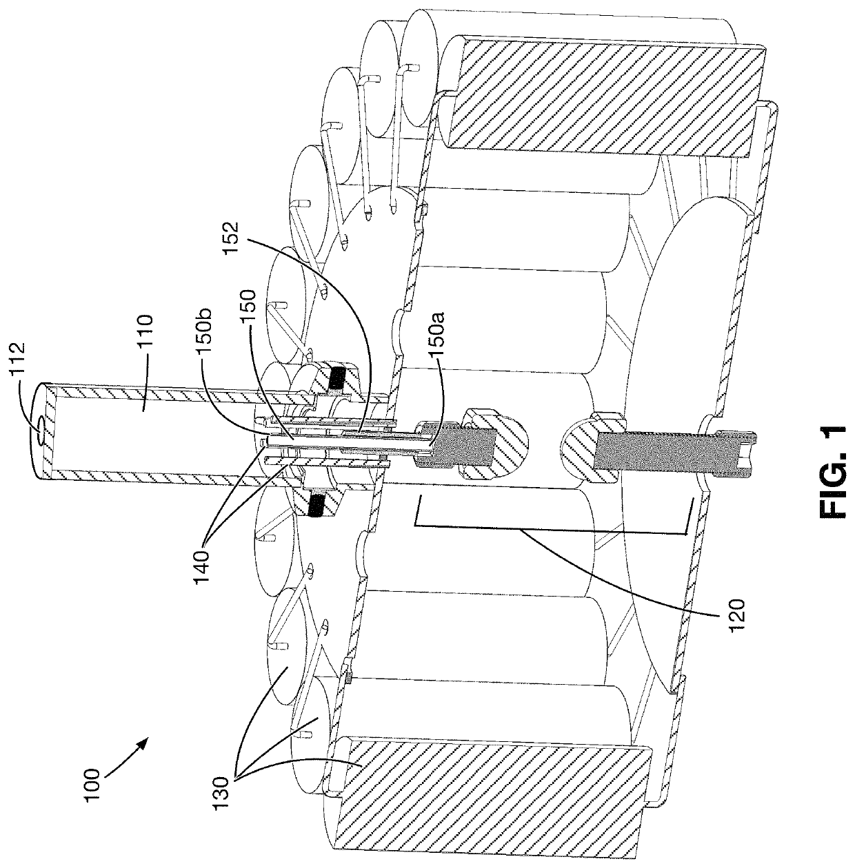
[0069]In a non-limiting example of the sizing and operation of the plasma focus apparatus 100 disclosed herein, the plasma focus apparatus 100 includes a plurality of parallel capacitors with a total stray inductance of 5 nH, the plurality of parallel capacitors being connected to a spark gap switch 120 with a 25 nH stray inductance and to a pair of collector plates, each with a 5 nH stray inductance. This example of the plasma focus apparatus 100 has a total stray inductance of 40 nH. When a pulsed voltage with a peak operating voltage of 10 kV is applied between the at least one outer and the inner electrode 150 of the exemplary plasma focus apparatus 100, the low total stray inductance enables the peak discharge, short-circuit current amplitude of the plurality of parallel capacitor to be at least 70 kA. (the short circuit current amplitude being calculated using the formula V / (L / C)0.5.
example 2
[0070]In a non-limiting example of the sizing and operation of the plasma focus apparatus 100 disclosed herein, the plasma focus apparatus 100 includes a plurality of parallel capacitors with a total stray inductance of 5 nH, the plurality of parallel capacitors being connected to a spark gap switch 120 with a 25 nH stray inductance and to a pair of collector plates, each with a 5 nH stray inductance. This example of the plasma focus apparatus 100 has a total stray inductance of 40 nH. When a pulsed voltage with a peak operating voltage of 6 kV is applied between the at least one outer and the inner electrode 150 of the exemplary plasma focus apparatus 100, the low total stray inductance enables the peak discharge, short-circuit current amplitude of the plurality of parallel capacitor to be at least 42 kA. (the short circuit current amplitude being calculated using the formula V / (L / C)0.5.
[0071]In an embodiment, the plasma focus apparatus 100 as disclosed herein is used for radiation...
example 3
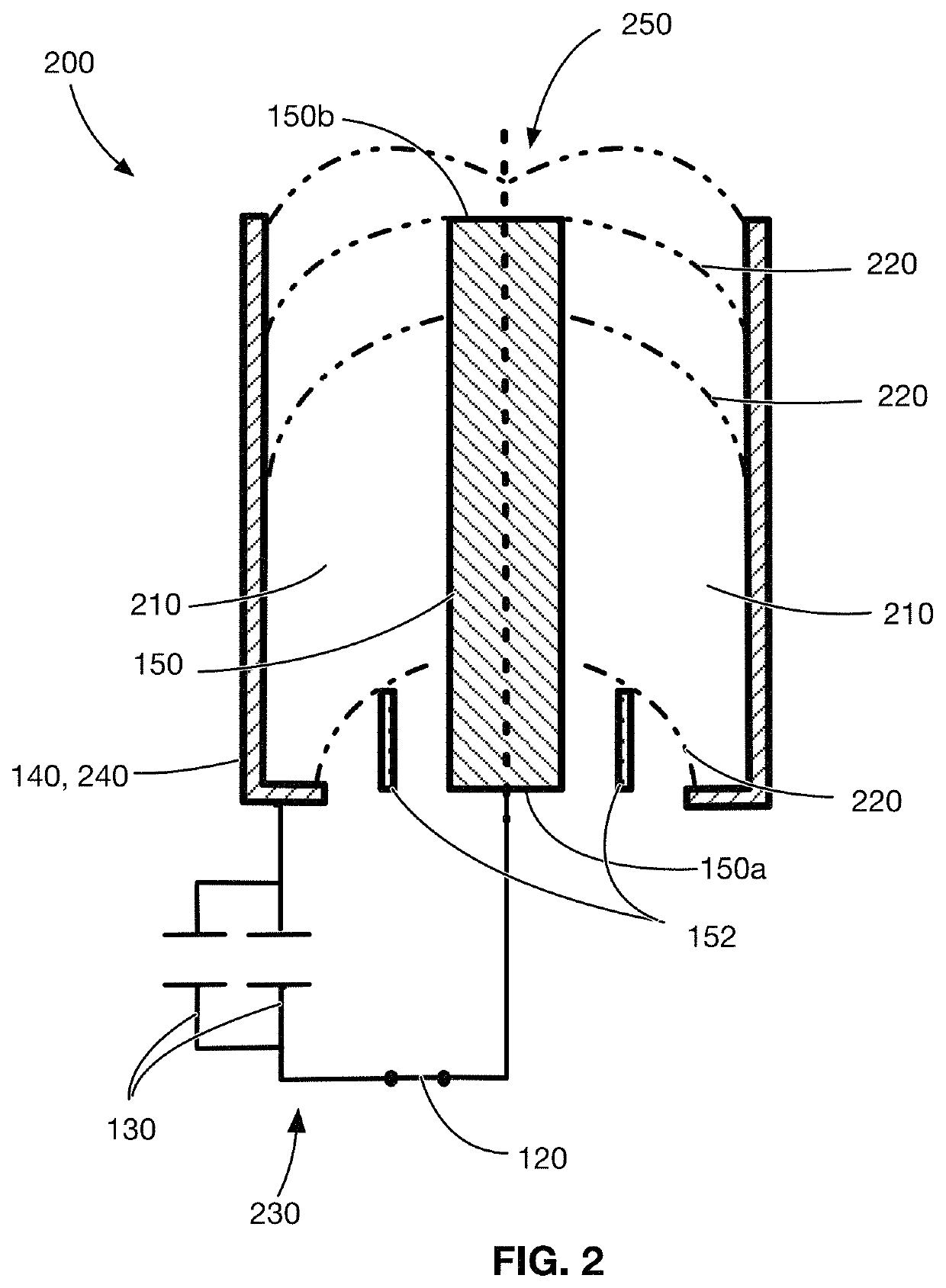
[0072]In an exemplary embodiment of the plasma focus apparatus 100 applied to generate radiation, the at least one outer electrode 140 is a single, tubular electrode having an inner diameter of 11 mm, the inner electrode 150 is a concentric electrode rod having an outer diameter of 3.5 mm and a length of 20 mm. In this example, the at least one working gas is Argon gas supplied at a pressure of 0.9 Torr. In this example, the power supply connected to the first collector plate provides a pulsed voltage with a 6 kV peak operating voltage to the pulsed power circuitry 230. The resulting current has a current linear density of 205 kA / (cm of at inner electrode 150 radius) and the speed factor (S) is 216 (kA / cm)Torr0.5. The resulting Argon all-line radiation peak power is 1.7 MW and the integrated all-line radiation yield is 1.5 mJ.
[0073]In an embodiment, the plasma focus apparatus 100 as disclosed herein is used for neutron generation. In this embodiment, the at least one working gas is ...
PUM
 Abstract
Description
Claims
Application Information