Passive intermodulation distortion measuring method and system

a measurement method and distortion technology, applied in the field of measurement methods and measurement systems, can solve problems such as communication outage, poor reception, and low level

Inactive Publication Date: 2010-11-25
NAT UNIV CORP YOKOHAMA NAT UNIV
View PDF3 Cites 46 Cited by
  • Summary
  • Abstract
  • Description
  • Claims
  • Application Information

AI Technical Summary

Problems solved by technology

Intermodulation is one of the phenomena that become problems in a broad frequency band for apparatuses, including an electronic apparatus operating in a low-frequency audio band and a wireless communication apparatus.
These intermodulation problems have been regarded as matters related to the nonlinearity of active components, such as an amplifier and a semiconductor device employed in the apparatus.
Further, in a case wherein the frequencies f1 and f2 are distant from each other, an even-number order PIM signal would become the cause of a poor reception.
This level is very low, compared with intermodulation distortion that is a problem for an active component.
However, a wireless communication apparatus that handles low level signals can not ignore this PIM.
In such a case, the PIM signal becomes a disturbance factor for a signal received at the same frequency f3, and a communication outage occurs.
The above described conventional PIM measurement method, however, has the following problems, and is not a satisfactory method.
The first problem is that the physical structure of a DUT is limited.
Therefore, in a case involving an evaluation of the relationship of the generation of the PIM to the individual transmission line parameters described above, it is difficult for only a single parameter to be independently controlled.
A second problem is a PIM that occurs at a terminator, which is required to absorb the electric power of a test signal passed through the DUT.
Therefore, when a special terminator is not prepared, PIM measurement at a low level is difficult, and it is hard for obtaining a wide dynamic range for a measurement system.
As described above, for a conventional PIM measurement system that assumes impedance matching condition, it is difficult for a large dynamic range to be stably obtained to perform a measurement.
As a problem that derives from the limitation on the structure of the above measurement sample, influence resulting from the size of the sample can not be ignored.
Furthermore, in a case wherein a plurality of PIM generation sources are locally present on the MSL, PIM signals produced by these PIM generation sources interfere with each other.
In addition, nonlinearity at the contact point of the connectors and the soldering point of the above described cables is also an obstacle to obtaining a precise PIM evaluation using the sample.
Moreover, the processing of the DUT is troublesome, and in a conventional PIM measurement system that assumes the performance of impedance matching condition using the terminator, it is difficult for a precise PIM measurement, for a conductive material, etc., to be performed.

Method used


Image

  • Passive intermodulation distortion measuring method and system
  • Passive intermodulation distortion measuring method and system
  • Passive intermodulation distortion measuring method and system

Examples


first embodiment

[0080]A PIM measurement method of a first embodiment is characterized in that a mismatching condition is provided between a transmission line, to which test signals are input, and a DUT, and a standing wave caused by mismatching is employed to measure a PIM signal that is generated by the DUT.

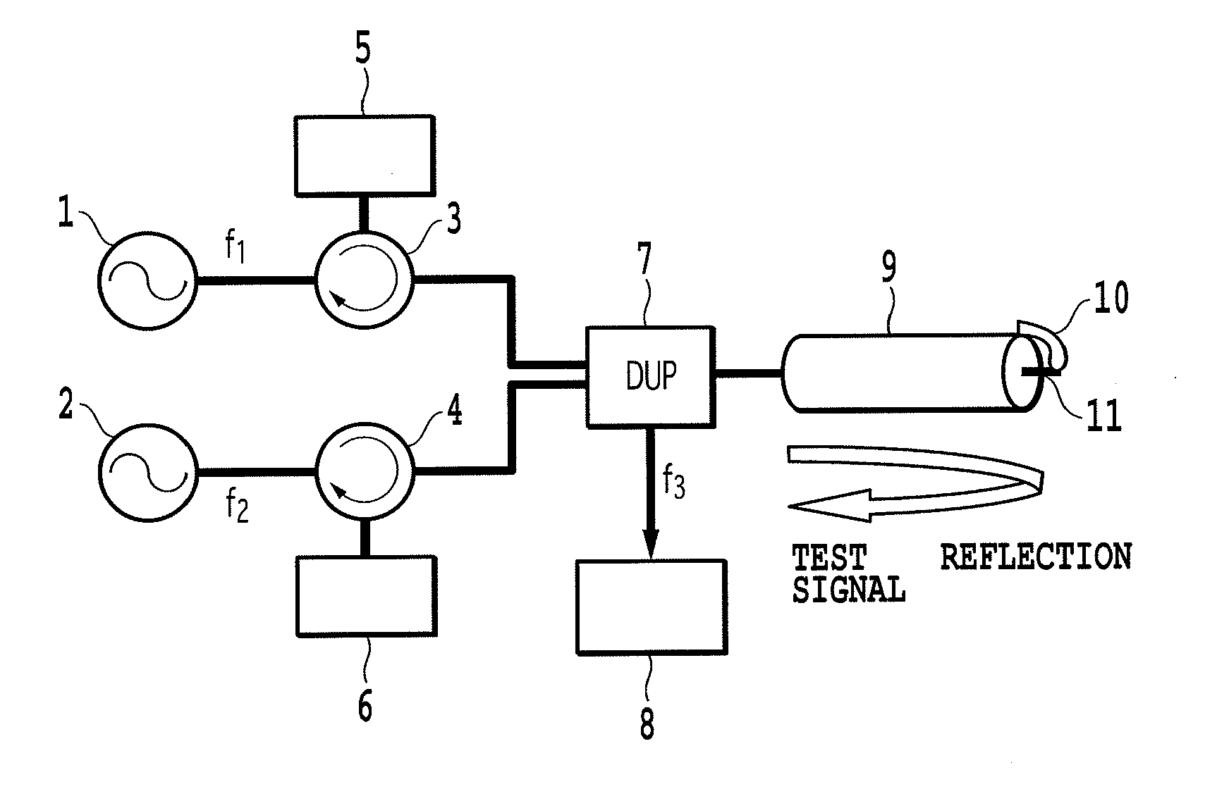
[0081]FIG. 1 is a diagram illustrating the arrangement of a measurement system used for the PIM measurement method according to the first embodiment of the present invention. The measurement system in FIG. 1 includes a section for generating a plurality of test signals and for terminating test signals that are reflected, a section for separating and detecting a PIM signal, and a transmission line section that includes a DUT. Test signals having different frequencies f1 and f2 are respectively output by test signal generation units 1 and 2. The test signal generation units 1 and 2 are, specifically, constituted by signal generators (SG), A-class amplifiers, etc. The test signal generation units ...

embodiment 1-1

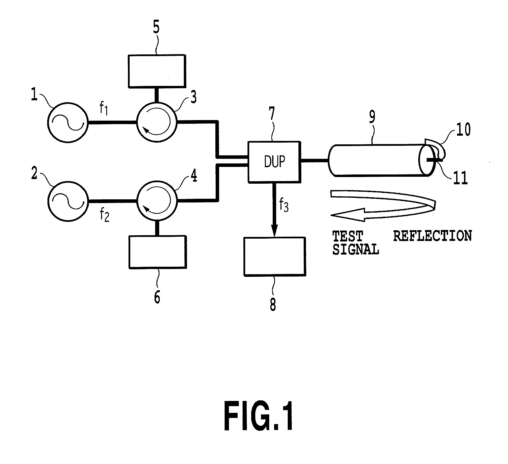
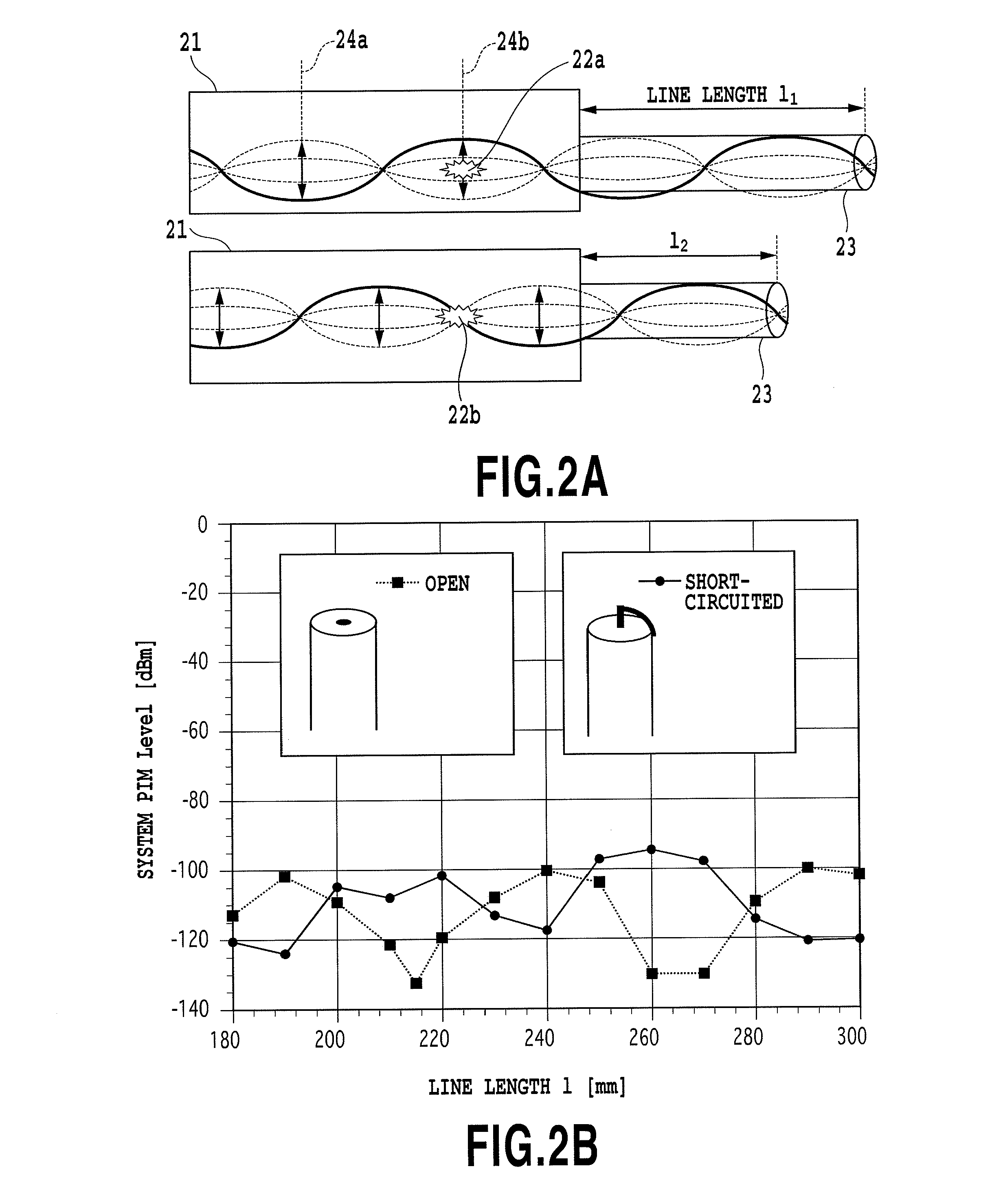
[0088]FIGS. 2A and 2B are diagrams for explaining the principle of system noise calibration by a PIM measurement method according to embodiment 1-1. FIG. 2A is a diagram for explaining the concept of system noise in the entire PIM measurement system for embodiment 1-1. In FIG. 2A, a transmission line 21 and a measurement system portion 21, which is a measurement system portion wherein a standing wave is generated, are conceptually shown. There is a case wherein the measurement system portion 21 includes a measurement system portion where a PIM is generated due to a factor other than a DUT, i.e., a system noise source 22a. Such portions are, for example, a contact point portion of a deteriorated connector, a soldered portion of a connector that is damaged by mechanical stress and the inside of the filter of a measurement apparatus. In order to perform a highly sensitive PIM measurement for a DUT, simply the length of a transmission line need be adjusted, so that the position of the s...

embodiment 1-2

[0100]The PIM measurement method for embodiment 1-1 is characterized by generating and employing a standing wave of test signals, without obtaining matching of a characteristic impedance for a DUT, which is required by the conventional PIM measurement method. The method in the above described embodiment employs a current standing wave by short circuiting the tip of a transmission line. However, the present invention is not limited to this method, and also focuses on and employs a voltage standing wave generated when the tip of a transmission line is open. When the tip of the transmission line is open, test signals are fully reflected at the tip portion, and a voltage standing wave of the test signals is generated along the transmission line. The tip of the transmission line corresponds to the position of the voltage anti-node of the voltage standing wave, and the voltage of the test signals becomes the highest. When the DUT is arranged at the open end of the transmission line, the h...


PUM


Abstract

According to a reception passive intermodulation measurement method of the present invention, a device under test is set to the mismatching condition, and a standing wave is generated on a transmission line where the sample is connected. Since the tip of the transmission line is short-circuited using the sample, the sample is positioned at the anti-node of the standing wave, and test signals are applied at a high current density. System noise is calibrated with the tip of the transmission line being open. Since impedance matching is not required and terminators are not employed, a large measurement dynamic range is obtained without being affected by passive intermodulation that is generated in terminators. The sample is very small, and an arbitrary shape can be selected. The property measurement is enabled for a wide range of materials, regardless of a conductive material, an insulating material and a magnetic material.

Description

TECHNICAL FIELD[0001]The present invention relates to a measurement method and a measurement system for an electric material, a magnetic material, etc., in a high frequency band. More specifically, the present invention relates to a method for employing passive intermodulation to measure an electromagnetic characteristic of an electric material, a magnetic material, etc., and a measurement system therefore.BACKGROUND ART[0002]Intermodulation is one of the phenomena that become problems in a broad frequency band for apparatuses, including an electronic apparatus operating in a low-frequency audio band and a wireless communication apparatus. Generally, intermodulation is generated as a distortion signal of a new frequency component when a low frequency electronic apparatus, a wireless communication apparatus or a semiconductor device receives or outputs a plurality of signals of different, but similar frequencies. In a low frequency band, for example, an analysis is performed based on...

Claims


Application Information

Patent Timeline
Patent Type & Authority Applications(United States)
IPC IPC(8): G01R23/02
CPCG01R23/20
Inventor KUGA, NOBUHIROYAMAMOTO, YASUYUKIDOI, MITSURUENDO, ATSUNORI
Owner NAT UNIV CORP YOKOHAMA NAT UNIV
Why Eureka
Try Eureka