
Fluid diffusion layers

Inactive Publication Date: 2007-04-19
BDF IP HLDG
View PDF23 Cites 47 Cited by
  • Summary
  • Abstract
  • Description
  • Claims
  • Application Information

AI Technical Summary

Benefits of technology

[0015] In one aspect of the present invention, a method of making a fluid diffusion layer comprises impregnating a porous, carbonaceous web with a matrix comprising a polymer having

Problems solved by technology

Woven and non-woven carbon fabrics and hydro-entangled felts tend to have more suitable mechanical and / or electrical properties, but contain a relatively large amount of carbon fibers, which is disadvantageous because of increased cost compared to carbon fiber papers.
However, the mechanical and / or electrical properties of carbon fiber papers alone may not be adequate to meet all the requirements for fuel cell applications.
Unfortunately, the carbonized phenolic matrix in such composites tends to be brittle.
This characteristic has generally limited the manufacture of GDL material to forming discrete sheets: phenolic-based composites are more susceptible to cracking and failure in roll-to-roll manufacturing processes; complex and costly web fiber blending and bonding cycles have been employed to reduce brittleness; but this undesirably increases manufacturing cost.

Method used


Image

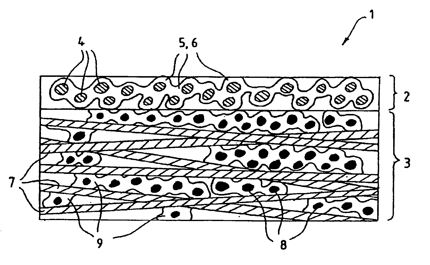
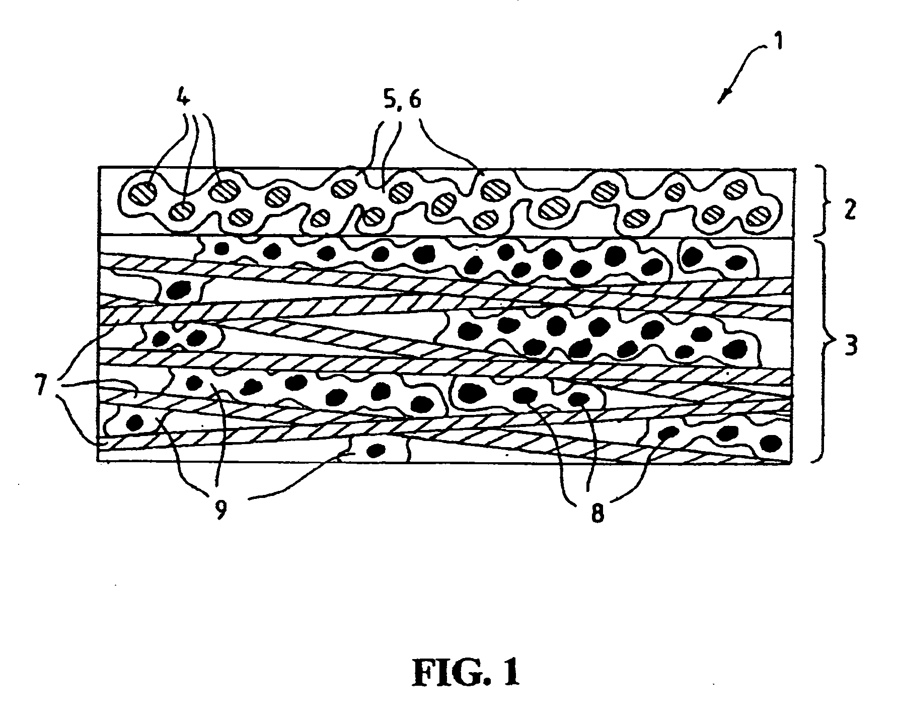
  • Fluid diffusion layers
  • Fluid diffusion layers
  • Fluid diffusion layers

Examples


example 3

Fluid Diffusion Layer

[0047] Samples of fluid diffusion layers were prepared in a like manner to those of Comparative Examples 1 except that the aqueous matrix formulation contained a blend of about 75% PVP, 25% phenolic resin, acrylic powder as an additional pore former and about 50% reduction of the carbon / graphite powder, as shown below.

Distilled water32.8% Methyl cellulose solution (4% by weight) 19%20% PVP solution 36%Phenolic resin2.7%Carbon / graphite powder4.7%Acrylic powder (30 μm mean diameter)4.8%

example 4

Fluid Diffusion Layer

[0048] Samples of fluid diffusion layers were prepared in a like manner to those of Example 3 except with a matrix formulation, as shown below, containing a blend of about 50% PVP, 50% phenolic resin, an addition of aerogel to the carbon / graphite fill powders, and a 20% reduction in overall solids content. This blend contained no additional pore forming aids in the matrix.

Distilled water58%Methyl cellulose solution (4% by weight)19%20% PVP solution13%Phenolic resin 3%Carbon / graphite powder 7%(17% aerogel carbon)

example 5

Fluid Diffusion Layer

[0049] Samples of fluid diffusion layers were prepared in a like manner and with the same matrix composition as Example 4, except a carbon fiber paper (Technical Fibre Products Limited, product number 20352B) having a weight per unit area of 25 g / m2 and approximately 325 micrometers thick was selected. The carbon fiber paper was impregnated with an aqueous mixture comprising:

Distilled water58%Methyl cellulose solution (4% by weight)19%20% PVP solution13%Phenolic resin 3%Carbon / graphite powder 7%(17% aerogel carbon)

[0050] Physical properties of fluid diffusion layers prepared in Comparative Example 1, and Examples 2 thru 5 are summarized in the following table.

TABLE 1EX-SITU TEST RESULTSComparativeComparativeExam-Exam-Exam-PropertyExample 1Example 2ple 3ple 4ple 5Gurley number:30184.84.24.6through-plane(sec)Gurley number:30083515323.6in-plane (sec)Taber - MD87.45.57.525Taber - XMD34.24.73.415Bulk density of0.2380.2230.1270.1250.096matrix fill(g / cc)Median por...


PUM

PropertyMeasurementUnit
Temperatureaaaaaaaaaa
Densityaaaaaaaaaa

Abstract

Fluid diffusion layers with favorable mechanical, physical and structural properties are prepared for fuel cell electrodes by: impregnating a porous carbonaceous web with a matrix comprising a polymer having pyrrolidone functionality and a high carbon char yield resin, such as activated aramid fiber pulp, lignins, phenolics, benzoxazines and phthalonitriles; and carbonizing the matrix. The polymer is optionally oxidized before carbonizing. The matrix may also include conductive fillers and / or pore formers. The fluid diffusion layers are particularly suitable for use in continuous roll-to-roll MEA processing of GDLs for use in solid polymer electrolyte fuel cells operating at high current densities and / or in highly humidified conditions.

Description

BACKGROUND OF THE INVENTION [0001] 1. Field of the Invention [0002] The present invention relates to methods of manufacture for fluid diffusion layers, in particular for fluid diffusion layers suitable for use as gas diffusion layers for solid polymer electrolyte fuel cells. [0003] 2. Description of the Related Art [0004] Solid polymer electrolyte fuel cells employ a membrane electrode assembly (“MEA”), which comprises the solid polymer electrolyte or ion exchange membrane disposed between the two electrodes. Each electrode comprises an appropriate catalyst, preferably located next to the solid polymer electrolyte. The catalyst may, for example, be a metal black, an alloy or a supported metal catalyst such as platinum on carbon. The catalyst may be disposed in a catalyst layer, and a catalyst layer typically contains ionomer, which may be similar to that used for the solid polymer electrolyte (for example, Nafion®). The catalyst layer may also contain a binder, such as polytetrafluo...

Claims


Application Information

Patent Timeline
IPC IPC(8): B05D3/02
CPCB01D67/0067B01D71/021B01D2323/12B01D2323/18H01M8/0234H01M8/0239C04B2235/616Y02E60/50C04B35/521C04B35/83C04B38/00C04B2235/5248C04B2235/5454H01M8/0241C04B38/0625C04B2111/00284C04B2111/00801C04B2111/00853C04B35/52
Inventor CONNORS, DONALD F. JR.GRANT, WILLIAM F.O'CONNOR, THOMAS J.GORDON, JOHN R.LOSZEWSKI, RAYMOND C.
Owner BDF IP HLDG
Learn More