Measuring device and method that operates according to the basic principles of confocal microscopy

a confocal microscopy and scanning system technology, applied in the field of scanning system based on the principle of confocal microscopy, can solve the problems of affecting the accuracy of a measurement made with such a procedure, affecting the accuracy of scanned data, and requiring several seconds or even longer, so as to improve the accuracy of scanned data, and improve the repeatability

Inactive Publication Date: 2010-03-16
SIRONA DENTAL SYSTEMS
View PDF13 Cites 64 Cited by
  • Summary
  • Abstract
  • Description
  • Claims
  • Application Information

AI Technical Summary

Benefits of technology

[0013]It is advantageous to select the influenced characteristic of the light from among the light intensity, its wavelength, and its spectrum. These characteristics are easily detected with CCD-sensors or CMOS-sensors
[0035]It is advantageous, in the context of a calibration, for the profile to be adapted to local conditions. This allows the effects of wear, for example as the decline in light intensity or the change in the characteristic curve of the installed light source, to be eliminated, and assures a precise analysis, even after long use of the light source. Further inaccuracies of the optical system can be determined by means of a calibration and correction data can be generated, which are applied to scanning data. This improves the accuracy of the scanned data.

Problems solved by technology

However, typically frame sequences of some 10 to 100 frames must be recorded, so that the measuring procedure, using established recording technologies, takes several seconds or even longer.
This suffers from the drawback that in order to improve the backscattered radiation it is necessary to coat the teeth.
The accuracy of a measurement made with such a procedure is low, however, since the entire depth range must be covered by a single image.

Method used


Image

  • Measuring device and method that operates according to the basic principles of confocal microscopy
  • Measuring device and method that operates according to the basic principles of confocal microscopy
  • Measuring device and method that operates according to the basic principles of confocal microscopy

Examples


Embodiment Construction

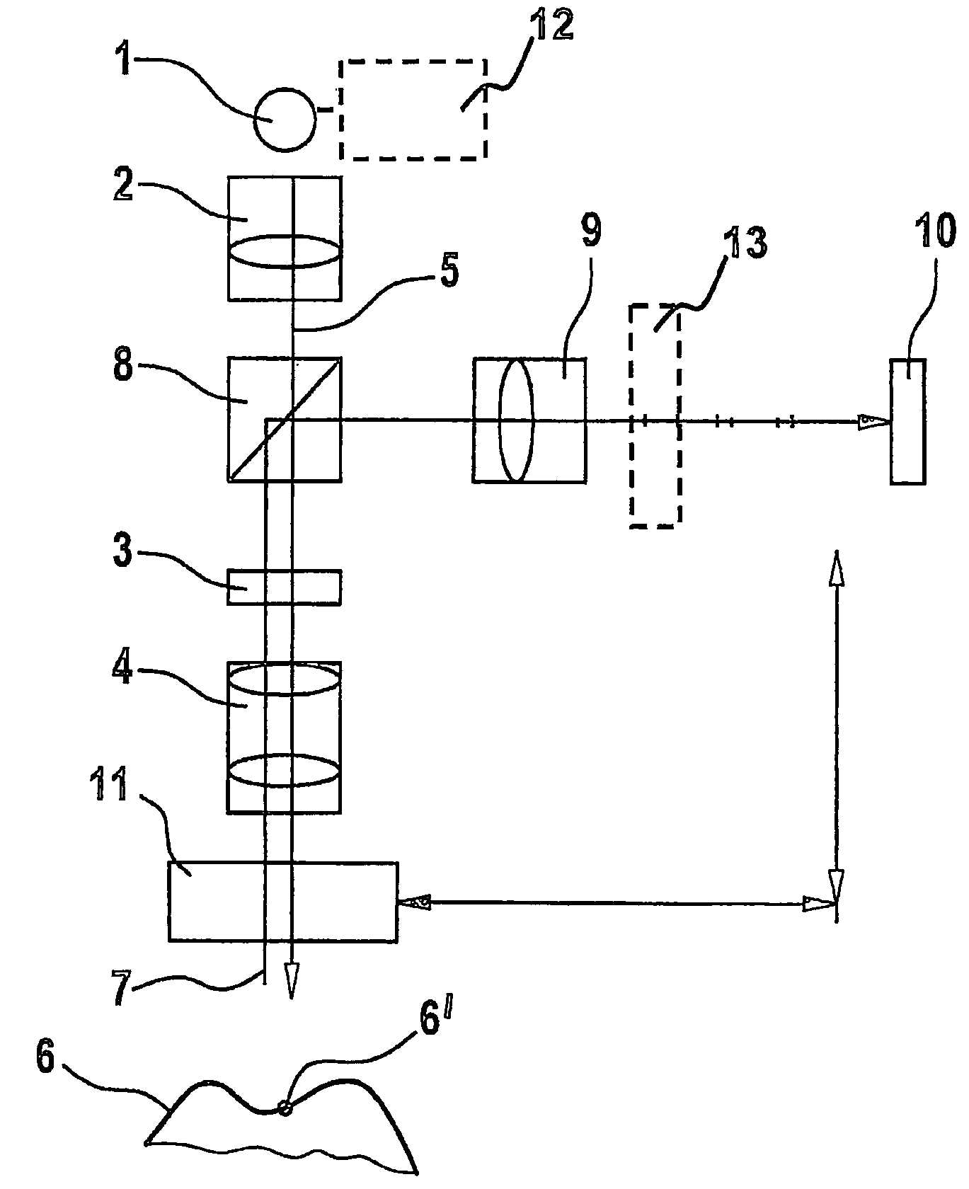
[0045]A confocal scanning apparatus as illustrated in FIG. 1 comprises, for example, a Nipkow Disk or a microlens array, a beam splitter, imaging optics, and means for varying the length of the optical path.

[0046]FIG. 1 shows a basic embodiment of the scanning system based on the principle of confocal microscopy. The scanning system comprises a light source 1, which typically radiates monochromatic or white light.

[0047]Through an optical system 2, the light source 1 is imaged in an appropriate way on an aperture array 3. The aperture array 3 can be designed as a locking plate with an array of holes, or alternatively, in more advanced applications, an arrangement of microlenses can be used. If necessary, this arrangement may be moved rapidly to achieve full coverage of the object 6, an exposure being necessary at each position.

[0048]By means of imaging optics 4, usually designed to be telecentric, the light 5 leaving the aperture array 3 is imaged onto an object 6 to be scanned. The ...


PUM

PropertyMeasurementUnit
lengthaaaaaaaaaa
optical distanceaaaaaaaaaa
heightaaaaaaaaaa

Abstract

A scanning system for confocal scanning of an object, comprising a light source (1), imaging optics (4) for focusing the light (5) radiated from the light source (1) onto the object (6) to be scanned, and further comprising an image detector (10) for detecting the light (7) from an object point (6′) backscattered from the object (6) and passing through the same imaging optics (4). Means (11) for varying the length of the optical path are disposed in the optical path between the aperture array (3) and the object (6), by which means the optical distance of the image plane can be modified in a specific manner, and means are provided to influence the light (5) radiated by the light source onto the object (6) and / or the light (7) reflected from the object (6) and impinging on the sensor (10), in at least one of its characteristics, during an exposure period (tB1) for acquiring an image, and, during said exposure period (tB1), a profile holds which states a specific relationship between the characteristic of the light (5, 7) and the optical distance of the image plane from the imaging optics (4), and means (10) are provided which provide a measured value dependent on the characteristics of the light of the trajectory of observation (7) over the exposure period (tB1), a height coordinate (Zs) of the object (6) being reconstructable from the measured value achieved during said exposure period (tB1) and a reference value.

Description

BACKGROUND OF THE INVENTION[0001]The invention relates to a scanning system based on the principle of confocal microscopy. Such scanning systems are used for scanning an object and enable both scanning of a point along an axis (two-dimensional scanning), and scanning of a surface disposed about an axis (three-dimensional scanning). Thus, such a device is suitable for a point sensor and a surface sensor. The invention relates in particular to free-hand intraoral scanning of uncoated teeth with a high degree of accuracy.DESCRIPTION OF THE PRIOR ART[0002]The basic principles of confocal 3D scanning are known. The determination of the height of a point on an object is achieved, an known from prior art, by determining, for each point of a locking of an aperture array, that position of the object, relative to the imaging optics or relative to the entire scanning device, at which the greatest amount of light beams back through the drilled locking board. In addition, during the movement of ...

Claims


Application Information

Patent Timeline
Patent Type & Authority Patents(United States)
IPC IPC(8): G01C11/12G01N21/00
CPCG02B21/0028G02B21/0064
Inventor SCHWOTZER, AXEL
Owner SIRONA DENTAL SYSTEMS
Why Eureka
Try Eureka