Electrical pressure contact

a pressure contact and electric technology, applied in the direction of coupling contact members, electrical appliances, coupling device connections, etc., can solve the problems of affecting the effectiveness of contact grease, affecting the use of degreasing cleaning means, etc., and achieves the effect of reducing the diameter of the contact element, preventing damage, and being held securely and stably in the bor

Active Publication Date: 2010-03-23
ERA CONTACT
View PDF24 Cites 35 Cited by
  • Summary
  • Abstract
  • Description
  • Claims
  • Application Information

AI Technical Summary

Benefits of technology

[0019]Advantageously, an assembly slit is formed in the wall of the contact element, which penetrates the contact element over its entire length. Thereby, the contact element is with the decrease of the assembly slit so together pressable, that the diameter of the contact element decreases. This advantageous further development of the invention enables the contact element to be easily compressed upon the assembly of the pressure contact and insertable in the bore formed in the connecting piece. Once inserted in the bore, the contact element again expands as a result of its elasticity, and is thus held securely and stably in the bore. Through this, the assembly of pressure contact is simplified.
[0020]Preferably, the contact element is located in interference fit in the bore of the connecting piece. This also simplifies the construction of the pressure contact.
[0021]In a preferred embodiment of the invention, the bore of the connecting piece has a larger diameter part, a smaller diameter part and a radially inward standing shoulder between these two parts. Thereby, the contact element is located in the larger diameter part and lies with an end against the shoulder. This embodiment enables the contact element to be assembled in a particularly simple manner in the bore of the connecting piece. Because the contact element is located in the larger diameter part of the bore, the away from the contact facing end of the contact head can be inserted through the contact element through until in the smaller diameter part of the bore. This allows a particular compact construction of the pressure contact with good mechanical guidance and secure contacting of the contact head.
[0022]In the preceding detailed further development, the length of the contact element is preferably equal to the length of the larger diameter part of the bore, while the outer diameters of the two ends of the contact element are equal to the diameter of the larger diameter part of the bore. The contact thus fills out the larger diameter part of the bore in its entire length and is radially fixed over its two ends in this part of the bore. This also simplifies the construction of the contact head.
[0023]Preferably, the away from the contact facing, smaller diameter portion of the contact head is completely inserted into the bore, when the contact head is maximally inserted in the housing sleeve, while it is only inserted in the larger diameter part of the bore with its away from the contact facing end, when the contact head maximally protrudes from the contact facing end of the housing sleeve. In this manner, the away from the contact facing portion of the contact head is still more securely guided into the bore of the connecting piece. Thereby, the length of the away from the contact facing, smaller diameter portion of the contact head preferably corresponds to the length of the bore. The axial dimensions of the pressure contact can thusly be reduced.
[0024]The contact element preferably comprises silver plated brass. This material distinguishes itself on the one hand through good conductivity and on the other hand through mechanical durability. Also this contributes to a good mechanical guidance as well as to guarantee a secure contact of the contact head.

Problems solved by technology

Also, the use of the degreasing cleaning means can be forgone, which, as described above, damages the effectiveness of the contact grease.

Method used


Image

  • Electrical pressure contact
  • Electrical pressure contact
  • Electrical pressure contact

Examples


Embodiment Construction

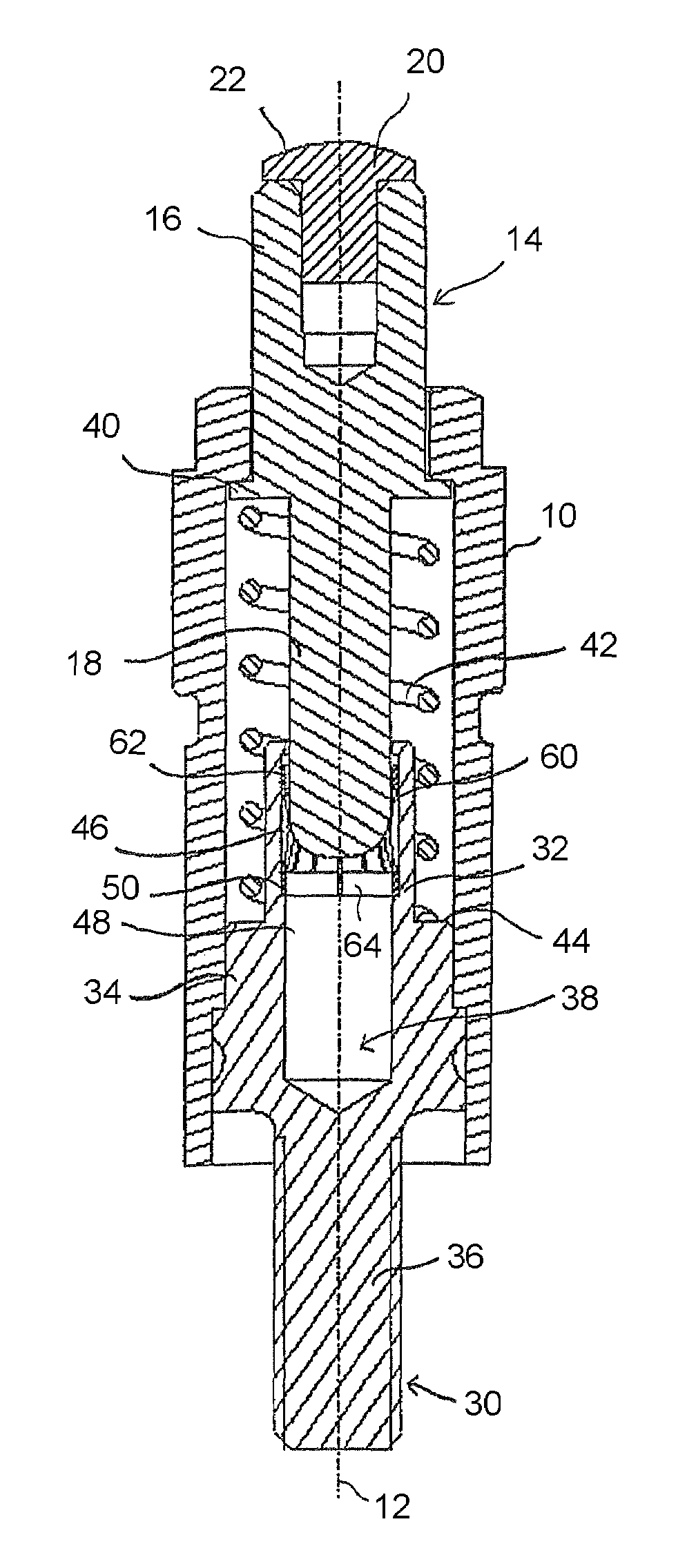
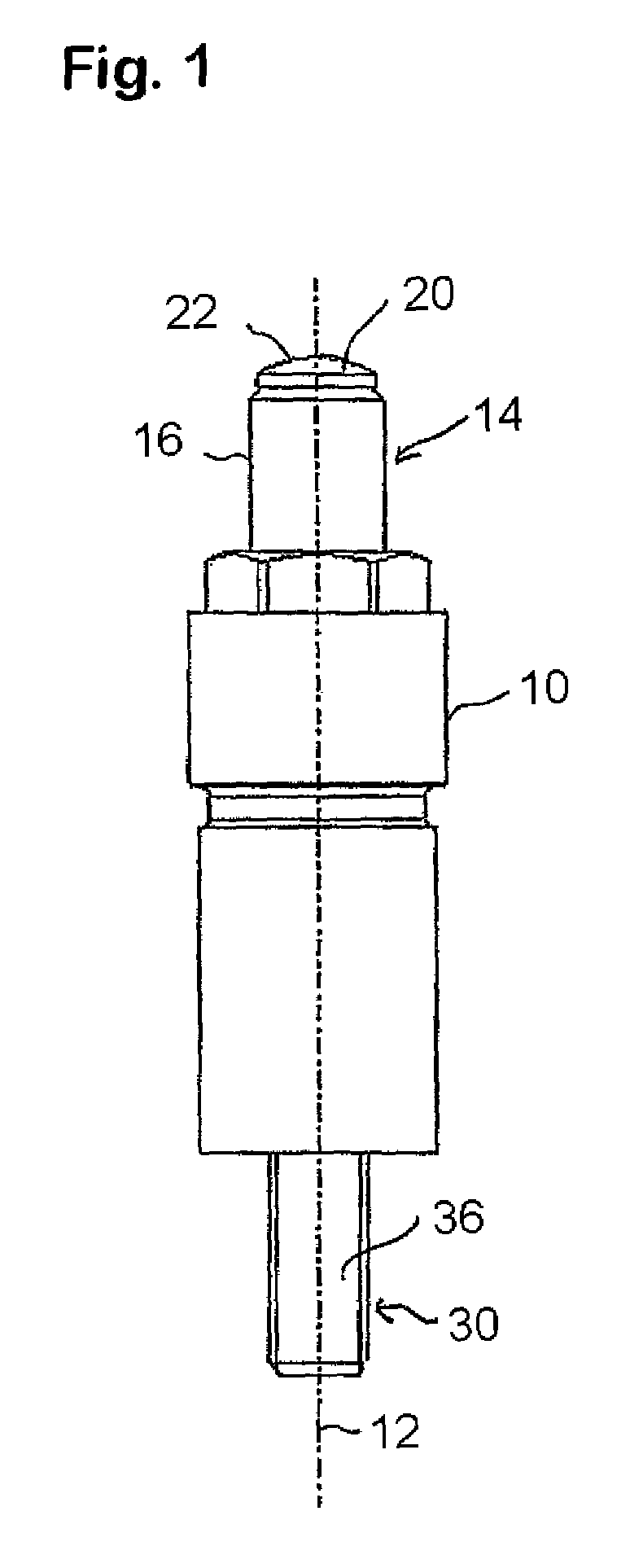
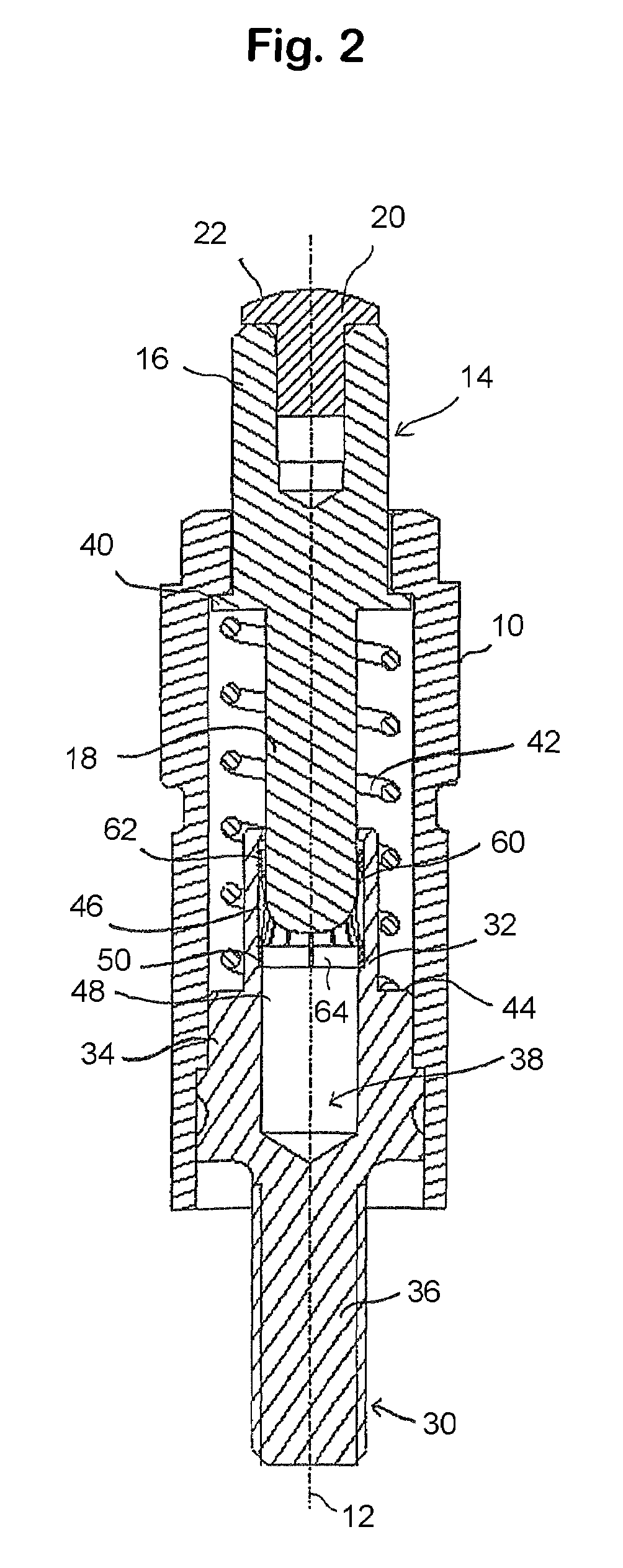
[0033]FIGS. 1 through 5 Illustrate an exemplary embodiment of the electrical pressure contact in accordance with the invention with a housing sleeve 10, which has a contact facing end, the upper end in FIGS. 1 and 2, and an away from the contact facing end, the lower end in FIGS. 1 and 2. The housing sleeve axis is indicated with reference number 12.

[0034]A contact head 14 is axially movably arranged in the housing sleeve 10. The contact head 14 has a first end or contact facing portion 16, which, in the condition of the pressure contact illustrated in FIG. 2, protrudes from the contact facing end of the housing sleeve 10, and a second end or an away from the contact facing portion 18, which is located within the housing sleeve 10 forming an elongated member. The diameter of the contact facing portion 16 is larger than that of the away from the contact facing portion 18.

[0035]In the contact facing end of the portion 16 of the contact head 14 is inserted a contact rivet 20, for examp...


PUM


Abstract

An electrical pressure contact device includes a sleeve with a first end and a second end. A contact head is slideably mounted in the sleeve and has a first end protruding from the sleeve and a second end located in the sleeve. A connecting piece has an inner portion connected to an inner wall of the sleeve and an outer portion protruding from the second end of the sleeve. An axially extending bore in a first piece located in the sleeve receives an elongated member of a second piece. A band has a plurality of inwardly arching lamellae and is located in the bore. The elongated member is inserted in the band so that the lamellae rub against the elongated member. A biasing element in the sleeve surrounds the elongated member and urges the contact head away from the sleeve.

Description

CROSS-REFERENCE TO RELATED APPLICATIONS[0001]This application is a National Stage of International Application No. PCT / EP2005 / 007638, filed Jul. 13, 2005. This application claims the benefit of German Application DE 10 2004 033 864.7, filed Jul. 13, 2004. The disclosures of the above applications are incorporated herein by reference.BACKGROUND OF THE INVENTION[0002]1. Technical Field[0003]The invention relates to an electrical pressure contact comprising a housing sleeve with an end facing the contact and an end facing away from the contact, a conductive contact head that is mounted in the housing sleeve so as to be movable in an axial direction, and which protrudes from the facing the contact end of the housing sleeve, a biasing element that is disposed within the housing sleeve, against whose biasing force the contact head is insertable in the housing sleeve, and a conductive connecting piece that is located at the away from the contact facing end of the housing sleeve for the att...

Claims


Application Information

Patent Timeline
Patent Type & Authority Patents(United States)
IPC IPC(8): H01R13/24
CPCH01R13/187H01R13/2421H01R13/111
Inventor KAINZ, ANDREAS
Owner ERA CONTACT
Why Eureka
Try Eureka