Engine control apparatus and engine operating method

a technology of engine control and operating method, which is applied in the direction of electrical control, separation processes, instruments, etc., can solve the problems of inability to notice such abnormalities, inability to reduce the reaction progress satisfactorily, and inability to meet the requirement of /sub>x /sub>removal rate, etc., to achieve the effect of restricting the movement of an automobil

Inactive Publication Date: 2010-03-30
NISSAN DIESEL MOTOR CO
View PDF23 Cites 48 Cited by
  • Summary
  • Abstract
  • Description
  • Claims
  • Application Information

AI Technical Summary

Benefits of technology

[0009]According to the present invention, when an abnormality occurs in an addition device so that a NOx reducing agent in an accurate amount cannot be added to exhaust gas of an engine, an output of the engine is restricted, and for example, an output characteristic of the engine relative to an accelerator operation by a driver is varied, and a fuel injection quantity is decreased than that at a normal time under the same accelerator operating amount. Therefore, it is possible to restrict the moving of an automobile in a state where NOx is not satisfactorily purified, and also to urge the driver to repair the addition device. Further, in addition to or in place of the restriction due to the alteration of the output characteristics, it is possible to restrict the moving and also to urge the repair of the addition device by inhibiting the restarting after an engine operation stops.

Problems solved by technology

However, such an SCR device as described in the above has the following problems.
In such a case, since an ammonia addition amount to the exhaust gas is changed, a ratio between NOx and ammonia is deviated from a proper value, so that the reduction reaction is not progressed satisfactorily and the NOx removal rate does not fulfill the requirement.
However, the abnormality occurred in the SCR device does not appear in the behavior of the automobile, and accordingly, a driver is unable to take notice of such an abnormality.
Further, even if measures for operating a warning light or an alert are taken, it may be considered that the driver fails to perform the prompt repair.

Method used


Image

  • Engine control apparatus and engine operating method
  • Engine control apparatus and engine operating method
  • Engine control apparatus and engine operating method

Examples


first embodiment

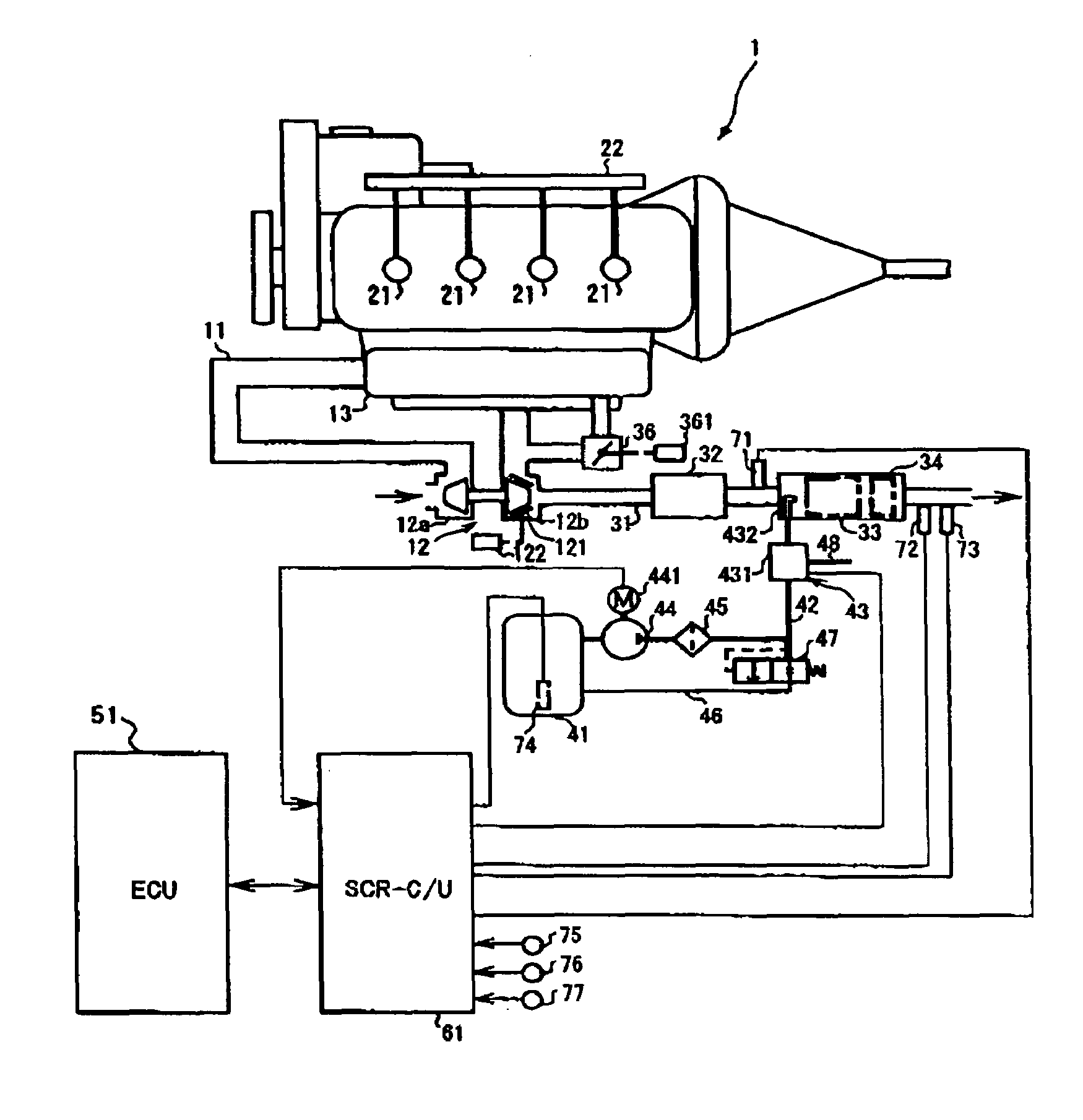
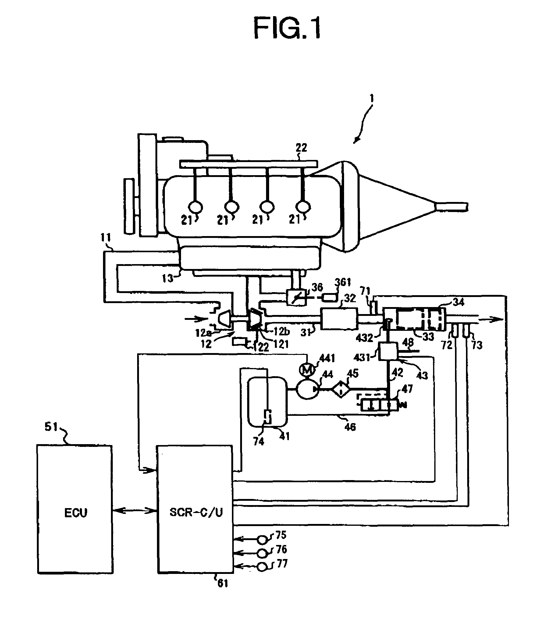
[0026]FIG. 1 shows an entire configuration of an automobile engine (to be referred to as an engine hereunder) according to the present invention. In the present embodiment, as an engine 1, a direct injection type diesel engine is adopted.

[0027]To an inlet portion of an intake passage 11, an air cleaner (not shown in the figure) is attached, and the dust in the intake air is removed by this air cleaner. In the intake passage 11, a compressor 12a of a variable nozzle type turbocharger 12 is disposed, so that the intake air is compressed by the compressor 12a to be sent out. The compressed intake air is flown into a surge tank 13, and is distributed to each cylinder via a manifold portion.

[0028]In the engine body, an injector 21 is disposed to a cylinder head for each cylinder. The injector 21 is operated according to a signal from an engine control unit (to be referred to as an engine C / U hereunder) 51. Fuel sent out by a fuel pump (not shown in the figure) is supplied via a common ra...

second embodiment

[0105]FIG. 9 shows a flowchart of a fuel injection quantity setting routine according to a This routine is also started when the ignition switch is turned on, and thereafter, is repetitively executed at each predetermined time. Each step in which the processing same as that in the flowchart shown in FIG. 7 is denoted by the same reference numeral.

[0106]In this routine, after the various operating conditions, such as the accelerator opening APO and the like, are read in (S401), in S601, the fuel injection quantity Of is set based on the read operating conditions. When it is judged that the abnormality judgment flag Fscr is 1 and accordingly, the abnormality occurs in the urea water injection system (S402), the connection between the starter and the power supply unit is broken (S404). After the vehicle speed VSP is read in (S405), it is judged that the read vehicle speed VSP is equal to or larger than the predetermined value VSP1, the routine proceeds to S602 where the previously set...

fourth embodiment

[0117]FIG. 11 shows a flowchart of a fuel injection quantity setting routine according to a This routine is started when the ignition switch is turned on, and thereafter, is repetitively executed at each predetermined time.

[0118]In this routine, the various operating conditions, such as the accelerator opening APO, the vehicle speed VSP and the like, are read in (S401), and based on the read operating conditions, the fuel injection quantity (corresponding to a second fuel supply quantity) Qf is set (S601). When it is judged that the abnormality judgment flag Fscr is 1 and accordingly, the abnormality occurs in the urea water injection system (S402), the connection between the starter and the power supply unit is broken (S404), and also, in S801, a restrictive injection quantity (corresponding to a first fuel supply quantity) Qflmt is set. The restrictive injection quantity Qflmt is set as one for restricting the output of the engine I at the time of the abnormality occurrence, and ...


PUM


Abstract

When an abnormality occurred in a SCR device is detected, the output of an engine is restricted. To this end, in one embodiment, at the time of an abnormality occurrence, a map adopted for calculating a fuel injection quantity is switched from that for a normal time (S407). Further, as the abnormality to be detected, the clogging of an injection nozzle, the dilution of urea water stored in a tank, or the like is adopted.

Description

[0001]This application is a continuation of PCT / JP2004 / 013307, filed on Sep. 13, 2004.BACKGROUND OF THE INVENTION[0002]1. Field of the Invention[0003]The present invention relates to an engine control apparatus and an engine operating method, and in particular, to a technology for purifying nitrogen oxides discharged from an automobile engine, using ammonia as a reducing agent.[0004]2. Description of the Related Art[0005]As a device for purifying air pollutants discharged from an engine, in particular, nitrogen oxides (to be referred to as NOx hereunder) in exhaust gas, using a secondary treatment, the following SCR (Selective Catalytic Reduction) device is known. This SCR device is installed in an exhaust passage of an engine, and is provided with an injection nozzle which injects an aqueous solution of ammonia or a precursor thereof. Ammonia (or ammonia obtained from the precursor) injected from the injection nozzle functions as a reducing agent, and reacts with NOx in the exhaust...

Claims


Application Information

Patent Timeline
Patent Type & Authority Patents(United States)
IPC IPC(8): F01N3/00B01D53/56B01D53/74F01N3/08B01D53/94F01N3/18F01N3/20F01N3/24F02B37/00F02D17/00F02D29/02F02D35/00F02D41/04F02D41/14F02D41/22
CPCF01N3/2066F01N11/00F02D41/1495F02D41/22F01N2550/05F01N2610/02F01N2610/08F01N2610/10F01N2610/14F01N2610/1406F01N2610/1493F01N2900/0422F02B37/00Y02T10/40Y02T10/47Y02T10/24Y02A50/20Y02T10/12
Inventor HIRATA, KIMINOBUESAKA, TAKEHIRO
Owner NISSAN DIESEL MOTOR CO
Why Eureka
Try Eureka