Rapid makeup drilling riser

a riser and makeup technology, applied in the direction of hose connection, sealing/packing, borehole/well accessories, etc., can solve the problems of increasing the danger level of performing the task, utilizing surface blowout preventors, and high pressure drilling risers, etc., to achieve rapid make-up, reduce diameter, and high preload

Active Publication Date: 2010-03-30
VETCO GRAY
View PDF19 Cites 56 Cited by
  • Summary
  • Abstract
  • Description
  • Claims
  • Application Information

AI Technical Summary

Benefits of technology

[0009]In order to secure the first riser pipe to the second riser pipe, a split actuation ring is repositioned inside the cavity of the housing assembly, forcing the profile of latch segment into engagement with the profile of the pin assembly by rotating the latch segments. The actuation ring is positioned by a series of load transfer blocks that are moved axially by a drive sleeve, which resides on the outside of the housing assembly. Alternatively, the load transfer blocks may directly act on the latch segments. The load transfer blocks travel in slots or windows that are milled into the housing assembly. Split actuation ring retainers hold the actuation ring in place. Retaining screws attach both the actuation ring retainer and actuation ring to the load transfer block. The drive sleeve may be controlled by an actuation device built in to a riser spider system. Seals and gaskets of the connector prevent leakage of fluid between the interior of the riser and the surrounding environment, the entry of sea water into the connector, and prevent high pressure bore fluid from passing into the cavity within the housing assembly.
[0013]The benefits of this connector over the prior art is that this connector is designed for rapid make-up while at the same time generating high preload which is able to withstand significant design separation loads.

Problems solved by technology

Additionally, high pressure drilling risers, utilizing surface blowout preventors, may be exposed to fill well bore pressure.
Both of these methods require manipulation with a wrench or stud tensioning device, placing personnel in close proximity to the drilling slots for prolonged periods of time, and increasing the danger level of performing the task.

Method used


Image

  • Rapid makeup drilling riser
  • Rapid makeup drilling riser
  • Rapid makeup drilling riser

Examples


Embodiment Construction

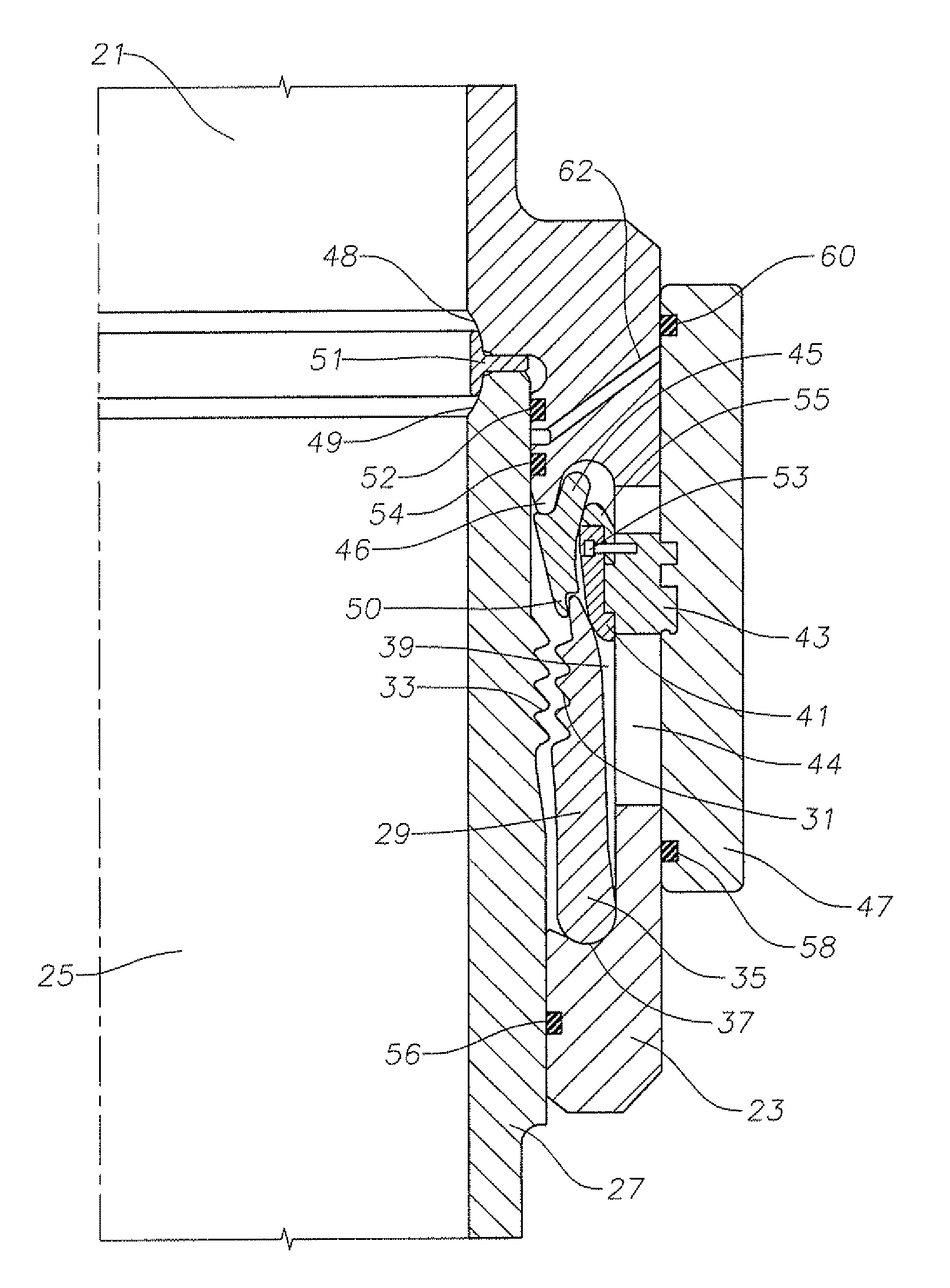
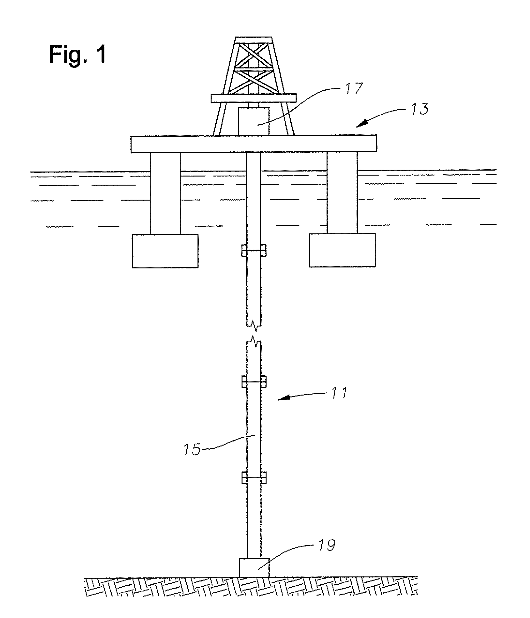
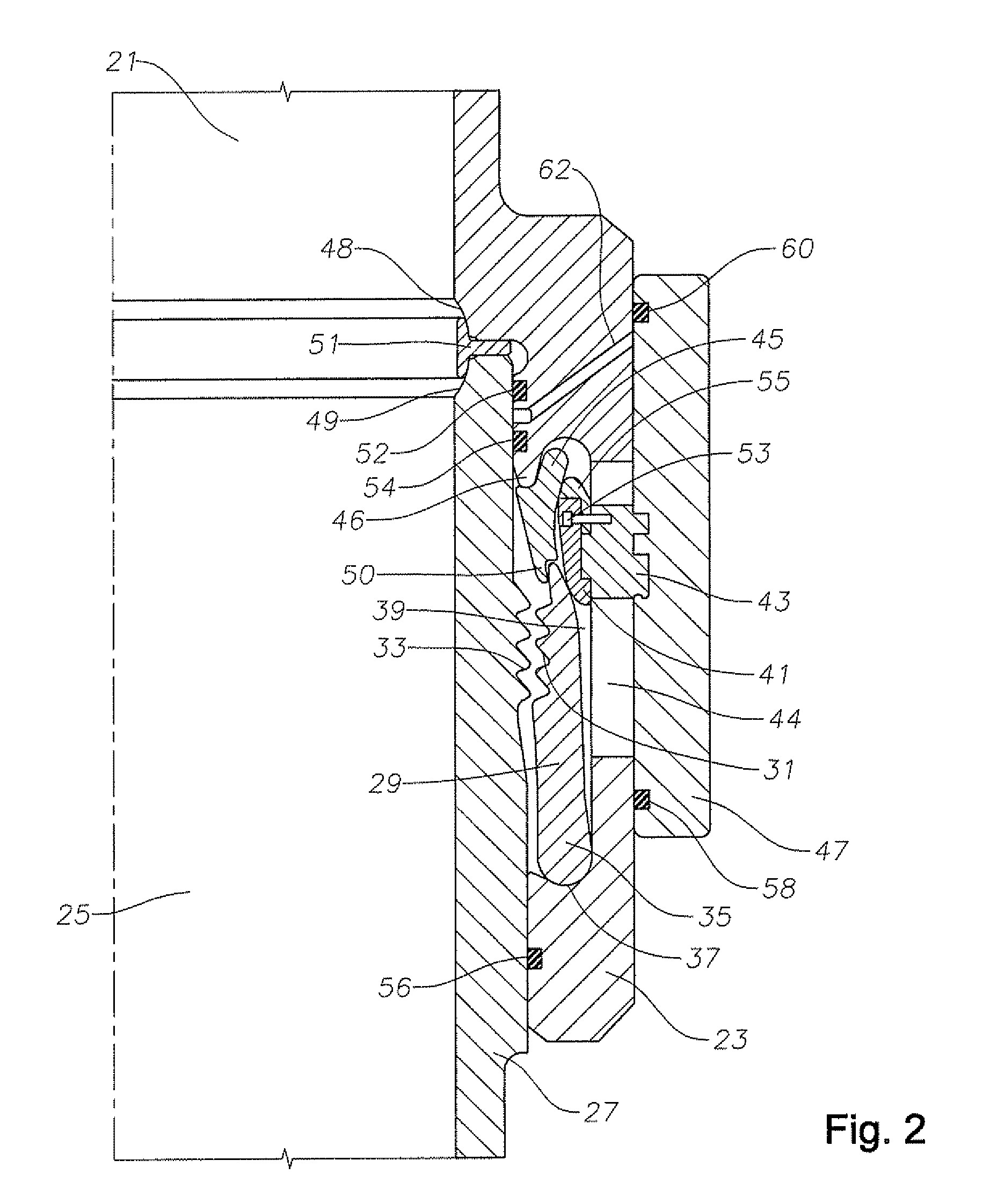
[0020]Referring to FIG. 1, a riser 11 is schematically shown extending from a floating platform 13. Platform 13 is illustrated schematically and can be any type, such as a spar, tension leg platform, mobile offshore drilling unit, or the like. Riser 11 is a drilling riser used to drill offshore wells and is particularly for use in applications where the blowout preventer is located at the surface. The drilling riser may be submerged for several years at a time, such as for use on a spar platform. The drilling riser may also be recovered after drilling each well, such as on a tension leg platform.

[0021]Riser 11 is made up of a plurality of high pressure riser joints 15, each approximately 60 feet in length. A blowout preventer 17 is shown schematically at the upper end of riser 11. A subsea tieback assembly 19 is shown schematically at the lower end of riser 11 although blowout preventer 17 can also be at the lower end. Locating blowout preventer 17 at the platform or near the surfac...


PUM


Abstract

A connector for connecting sections of drilling riser pipe wherein a first riser contains a pin assembly with an external first grooved profile and a second riser contains a housing assembly. An internal split pivoting latch segment assembly carried by the housing assembly contains a second grooved profile adapted to mate to the first grooved profile and a split actuation ring movably carried by the housing assembly forces the second grooved profile of the latch segment assembly into engagement with the first grooved profile of the pin assembly. A plurality of retraction links engage an upper edge of the latch segment assembly to disengage the second grooved profile of the latch segment assembly from the first grooved profile of the pin assembly if the risers are to be disconnected.

Description

CROSS-REFERENCE TO RELATED APPLICATION[0001]This application claims priority to provisional application 60 / 801,667, filed May 19, 2006.FIELD OF THE INVENTION[0002]This invention relates in general to high pressure riser systems with surface or near surface blowout preventers and more particularly to a high strength, high preload, rapid makeup connector for such riser systems.DESCRIPTION OF THE PRIOR ART[0003]A drilling riser is a large diameter pipe used in offshore drilling operations to guide the drill string from the offshore platform to and from the subsea wellhead and to provide means for circulation of drilling fluid. The drill string is lowered through the drilling riser. Drilling fluid circulates down from the platform through the drill string, out through the drill bit, and returns to the platform in the space between the inner diameter of the riser and outer diameter of the drill string. Environmental forces caused by waves, currents and the movement of the offshore platfo...

Claims


Application Information

Patent Timeline
Patent Type & Authority Patents(United States)
IPC IPC(8): E21B17/01
CPCE21B17/085E21B33/038F16L37/002Y10S285/92E21B17/08
Inventor PALLINI, JOSEPH W.STEWART, SCOTT I.WONG, STEVE M.HAVELKA, DANIEL L.
Owner VETCO GRAY
Why Eureka
Try Eureka