Smart card with extended surface module

a module and module technology, applied in the field of smart cards, can solve the problems of poor fixing of the module, manufacturing problems, and the arrangement used at present, and achieve the effects of increasing the gluing surface of the module, increasing the reliability of the card, and increasing the gluing surfa

Inactive Publication Date: 2010-03-30
GEMPLU
View PDF23 Cites 14 Cited by
  • Summary
  • Abstract
  • Description
  • Claims
  • Application Information

AI Technical Summary

Benefits of technology

[0010]In the case of a module comprising a chip of current standard size (that is approximately 10 mm×8 mm including the drop of protective resin), the solution of the invention makes it possible to-increase the gluing surface for the module on the card and therefore increase the reliability of said card. This increase in the gluing surface is obtained by increasing the surface of the support supporting the chip.
[0011]And above all, the invention allows reliable fixing of large-sized modules provided with one or more large-sized chips. This is because it is possible to increase the size of the second cavity without reducing the gluing surface for the module on the card.
[0012]The invention simplifies the method of manufacturing the card simplifying the step of moulding at the edge of the card in question, by elimination of the thin wall present along the edge of the card.

Problems solved by technology

The arrangement used at present has several problems.
The gluing surface for the module support can prove to be insufficient and lead to poor fixing of said module, in particular in the case of a large-sized chip.
Consequently, the greater the total surface of the chip or chips, the more insufficient this gluing surface proves to be since the ratio of module surface to gluing surface decreases.
This arrangement also poses manufacturing problems.
In fact it is difficult and even impossible to reduce this distance, since it is impossible to inject the plastic material onto a very thin wall.

Method used


Image

  • Smart card with extended surface module
  • Smart card with extended surface module

Examples


Embodiment Construction

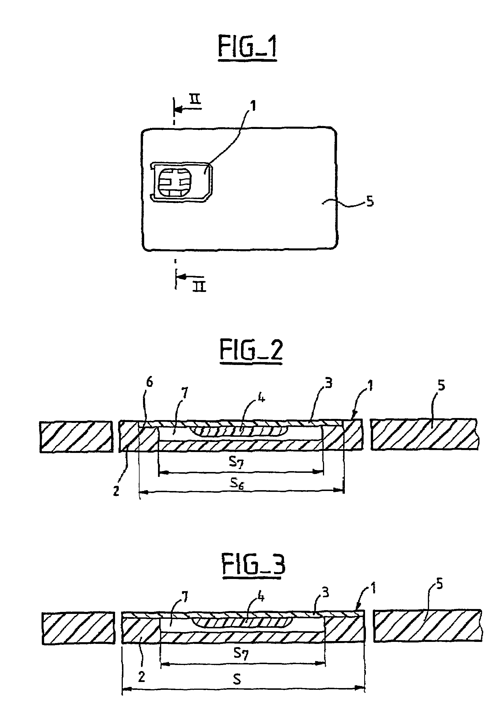
[0021]The following description relates to a SIM mini-card for portable telephony, but the invention applies to any smart card, irrespective of its format and irrespective of its application.

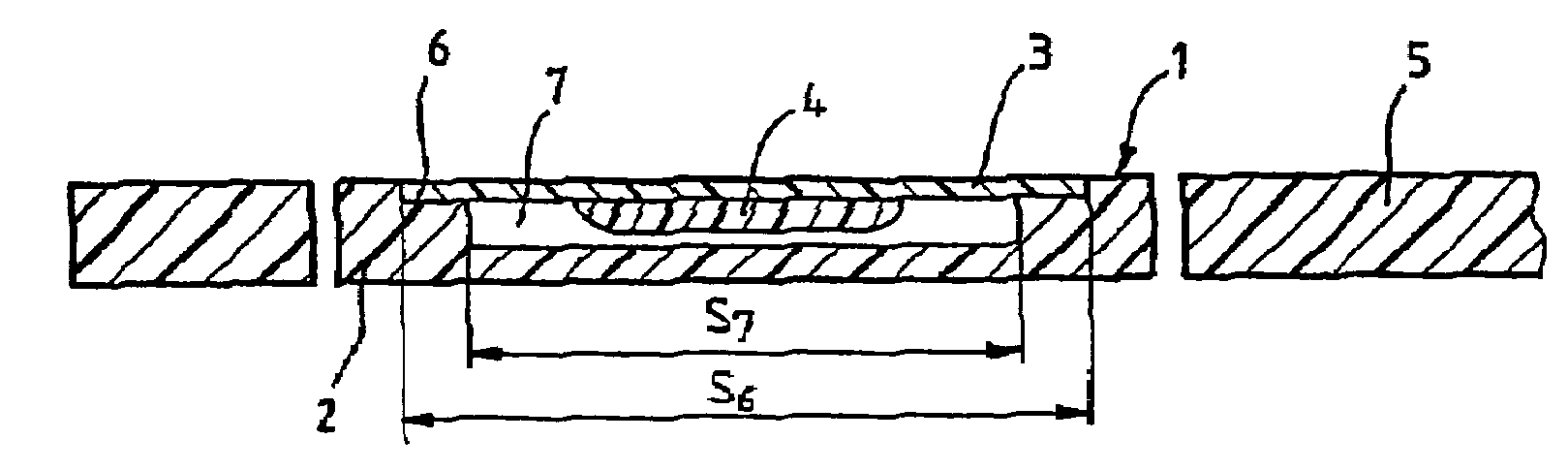
[0022]A smart card 1 consists of a card made of plastic material of standardised format 2. It bears an electronic module consisting of a support 3 formed from a sheet of plastic material possibly provided with printed circuits and supporting an electronic chip 4, for example an electronic memory. As a general rule, this chip 4 is glued on a face of the support 3 and protected by a coat of epoxy resin forming an extra thickness on the support.

[0023]The figures depict a mini-card 1 attached to a support card of “bank card” format 5 having only a presentation function. In order to use the mini-card 1, it is detached by virtue of cuttable tongues surrounding it.

[0024]FIGS. 1 and 2 depict a smart card 1 according to the prior art.

[0025]For fixing the module 3, 4 on the card 2, the latter comprises a ...


PUM


Abstract

A smart card includes a card bearing a module that is made up of a support supporting at least an electronic chip. The support is fixed on one surface of the card. This surface extends up to at least one of the edges of the card.

Description

[0001]This disclosure is based upon French Application No. 01 / 17054, filed Dec. 20, 2001, and International Application No. PCT / FR02 / 04429, filed on Dec. 18, 2002, the contents of which are incorporated herein by reference.BACKGROUND OF THE INVENTION[0002]The present invention concerns a smart card and more precisely a smart card comprising a card bearing a module consisting of a support itself supporting at least one electronic chip, said support being fixed on a surface of the card.[0003]A known smart card consists of a card made of plastic material of standardised format, two formats of which are the “bank card” type defined by ISO 7810 and the SIM “mini-card” type for mobile telephony. It bears an electronic module consisting of a support formed from a sheet of dielectric material possibly provided with printed circuits and supporting an electronic chip, for example an electronic memory. As a general rule, this chip is glued on one face of the support and protected by a coat of ...

Claims


Application Information

Patent Timeline
Patent Type & Authority Patents(United States)
IPC IPC(8): G06K19/06B42D15/10G06K19/077
CPCG06K19/07739G06K19/07745H01L2924/0002H01L2924/00
Inventor ODDOU, LAURENTOTTOBON, STEPHANE
Owner GEMPLU
Why Eureka
Try Eureka