Diagnosis device of capacitor discharge ignition device for engine

a technology of ignition device and diagnostic device, which is applied in the direction of engine ignition, engine controller, machine/engine, etc., can solve the problem of inability to accurately determine the ignition devi

Active Publication Date: 2010-03-30
MAHLE INT GMBH
View PDF3 Cites 2 Cited by
  • Summary
  • Abstract
  • Description
  • Claims
  • Application Information

AI Technical Summary

Benefits of technology

[0010]The present invention has an object to provide a diagnosis device of a capacitor discharge ignition device for an engine that can properly detect an abnormality of an ignition power supply portion and also an abnormality of an ignition coil.

Problems solved by technology

Abnormalities that occur in a capacitor discharge ignition device include a break in a component that constitutes an ignition circuit, an abnormality that occurs in an ignition circuit such as a short circuit or a wire break, an abnormality of an ignition power supply portion such that a charging power supply voltage is not applied to an ignition capacitor due to an improper connection between the ignition power supply portion and the ignition circuit, and an abnormality of an ignition coil such as a break in a primary coil of an ignition coil or a disconnection of a wire connecting between the ignition coil and the ignition circuit.
In this case, when the ignition power supply portion is normal and the ignition power supply portion normally outputs a capacitor charging voltage, the diagnosis device detects the output voltage of the ignition power supply portion as a charging voltage of the ignition capacitor even if there is an abnormality in the ignition coil, and when the value of the detected voltage is the value or more of a normal charging voltage across the ignition capacitor, it is improperly determined that the ignition device is normal though it is abnormal.

Method used


Image

  • Diagnosis device of capacitor discharge ignition device for engine
  • Diagnosis device of capacitor discharge ignition device for engine
  • Diagnosis device of capacitor discharge ignition device for engine

Examples


Embodiment Construction

[0047]Now, preferred embodiments of the present invention will be described in detail with reference to the drawings.

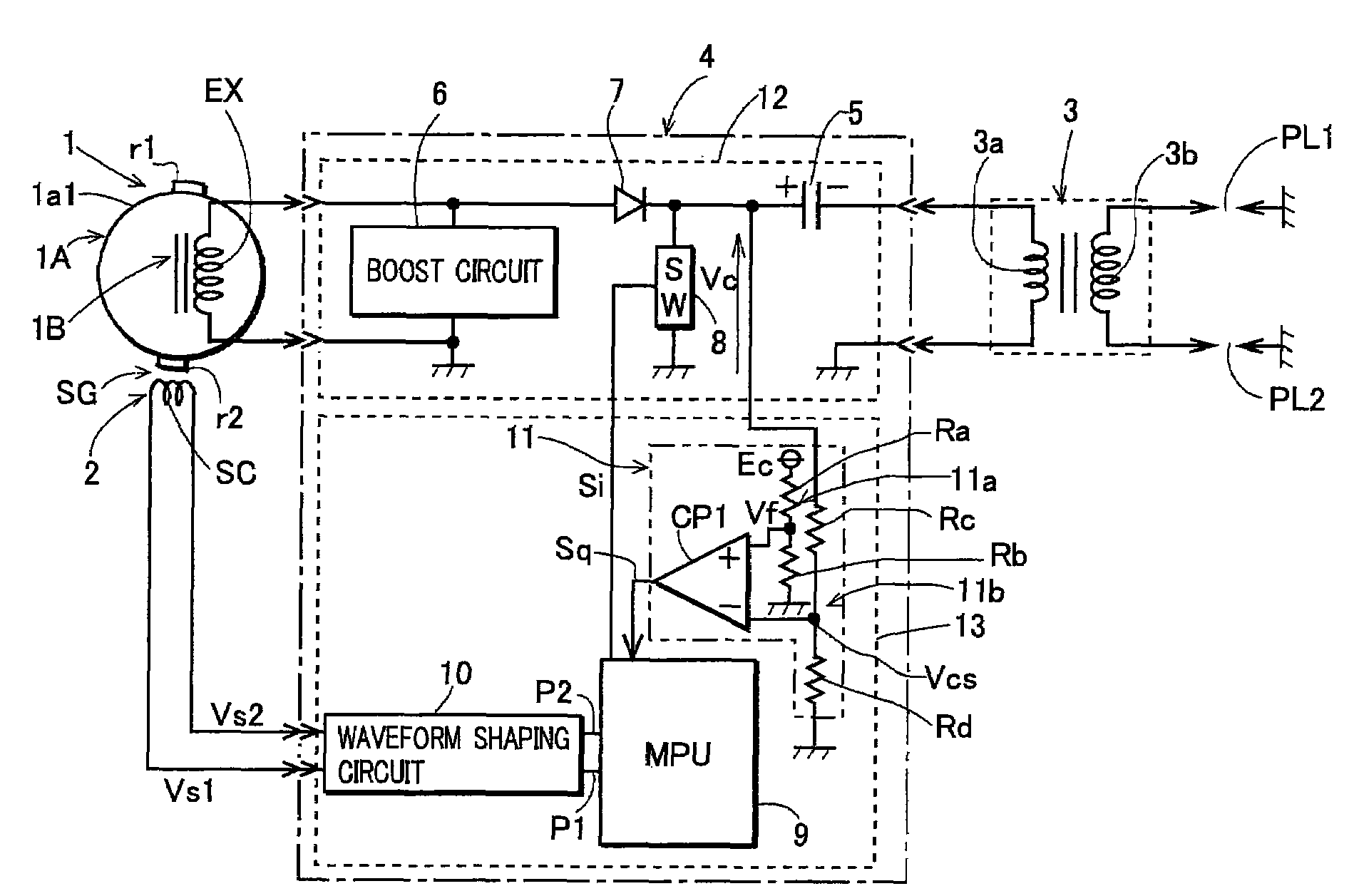
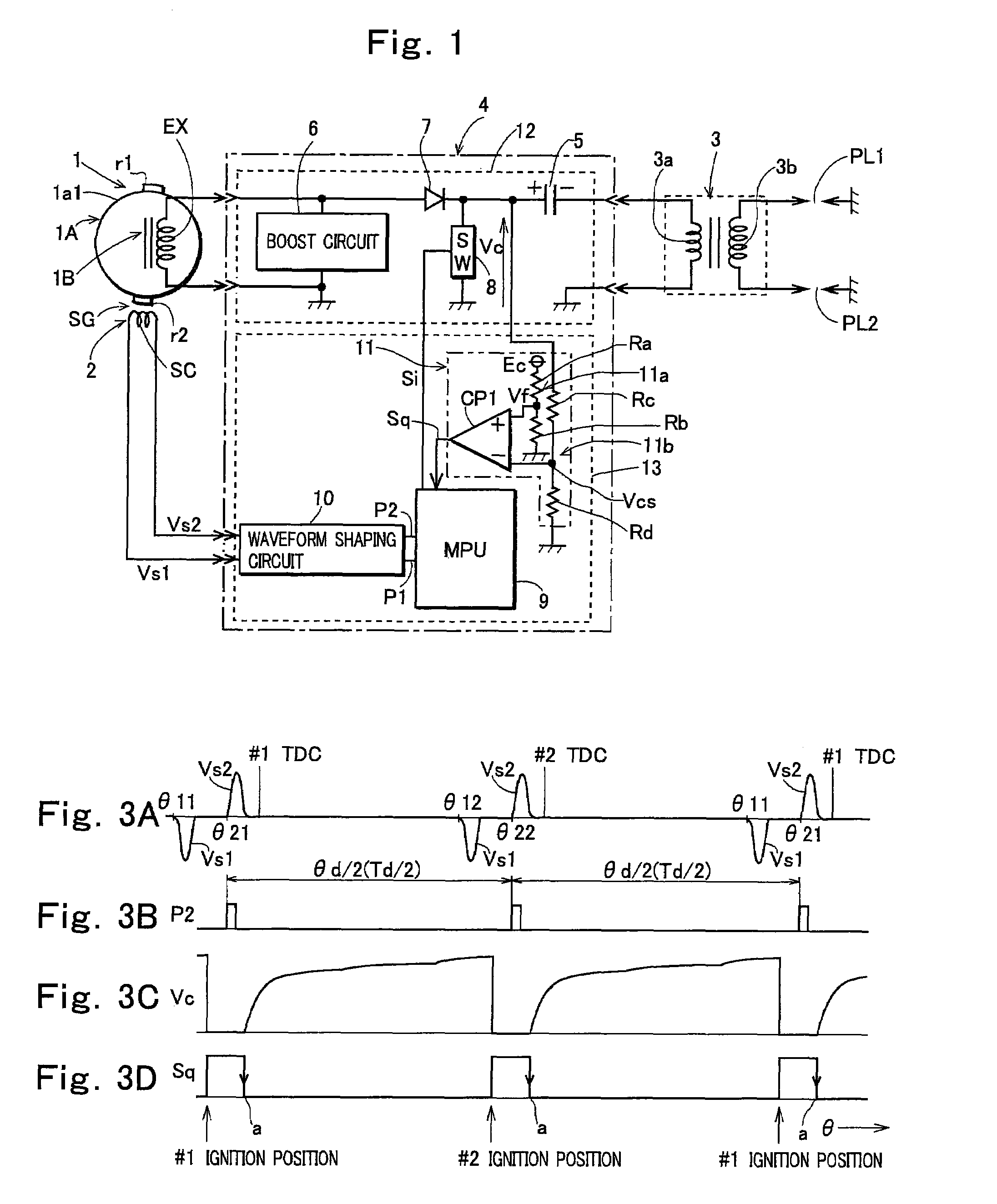
[0048]FIG. 1 shows a construction of an ignition device according to a first embodiment of the present invention. In FIG. 1, a reference numeral 1 denotes a magneto generator driven by an unshown engine. The generator is comprised of a rotor 1A mounted to a crankshaft of the engine, and a stator 1B mounted to a case or the like of the engine. The rotor 1A includes a cup-like rotor yoke 1a1, and a permanent magnet (not shown) mounted to an inner periphery of a peripheral wall portion of the rotor yoke. The stator 1B includes a stator iron core having a magnetic pole portion facing a magnetic pole of the rotor, and an exciter coil EX wound around the stator iron core.

[0049]The present invention may be applied to a two-cycle engine and a four-cycle engine, and a two-cycle engine is herein exemplified having two cylinders ignited at 180° intervals.

[0050]On an outer periph...


PUM


Abstract

A diagnosis device of a capacitor discharge ignition device for an engine that detects, as a singularity, a leading edge or a trailing edge of a voltage between output terminals of an ignition power supply portion that generates a voltage for charging an ignition capacitor, counts the number of singularities detected while a crankshaft rotates through a measurement section, which is a section of a certain crank angle determined with reference to a pulse signal obtained by a signal generator that generates a pulse signal at a specific crank angle position of an engine, and diagnoses an abnormality of the ignition device and a cause of the abnormality by comparing the count value of singularity with the number of times of normal ignition of the engine performed while the crankshaft rotates through the measurement section.

Description

TECHNICAL FIELD OF THE INVENTION[0001]The present invention relates to a diagnosis device that diagnoses an abnormality of a capacitor discharge ignition device for an engine and a cause of the abnormality.PRIOR ART OF THE INVENTION[0002]An engine control device that controls electrical components such as an ignition device or a fuel injection device using a microprocessor desirably has a diagnosis function (self diagnosis function) so as to store history of abnormalities that occur in the electrical components and causes of the abnormalities for proper maintenance or repair of the engine.[0003]To provide the control device with the self diagnosis function, information on operation states of the electrical components needs to be provided to a microprocessor so as to determine whether there is an abnormality. When it is detected that there is an abnormality in any of the electrical components, it is desirable that a cause of the abnormality can be specified.[0004]The present inventio...

Claims


Application Information

Patent Timeline
Patent Type & Authority Patents(United States)
IPC IPC(8): F02P17/00
CPCF02P3/06F02P17/00F02D2200/503
Inventor SHIMAZAKI, MITSUYOSHIKAWAGOE, JUN
Owner MAHLE INT GMBH
Why Eureka
Try Eureka