
Non-contact oil spill detection apparatus and method

a technology of oil spill detection and non-contact, applied in the direction of luminescent dosimeters, optical radiation measurement, fluorescence/phosphorescence, etc., can solve the problems of large oil spills and leakages, large and small, and previous in-water systems developed for monitoring bodies of water have required substantial maintenance, and flow-through systems are susceptible to bio-fouling and oil staining, etc., to achieve effective operation, reliable detection signal, and effective reduction of background interference

Active Publication Date: 2010-03-30
INTEROCEAN SYST LLC
View PDF4 Cites 28 Cited by
  • Summary
  • Abstract
  • Description
  • Claims
  • Application Information

AI Technical Summary

Benefits of technology

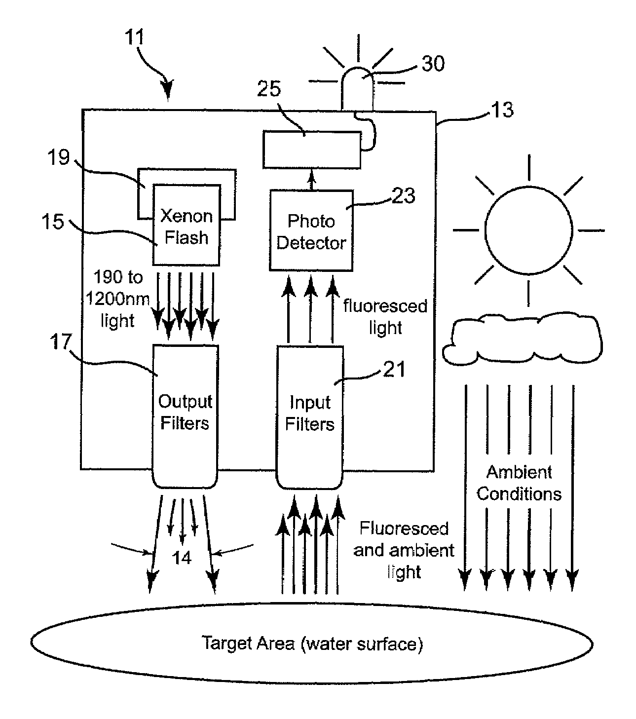
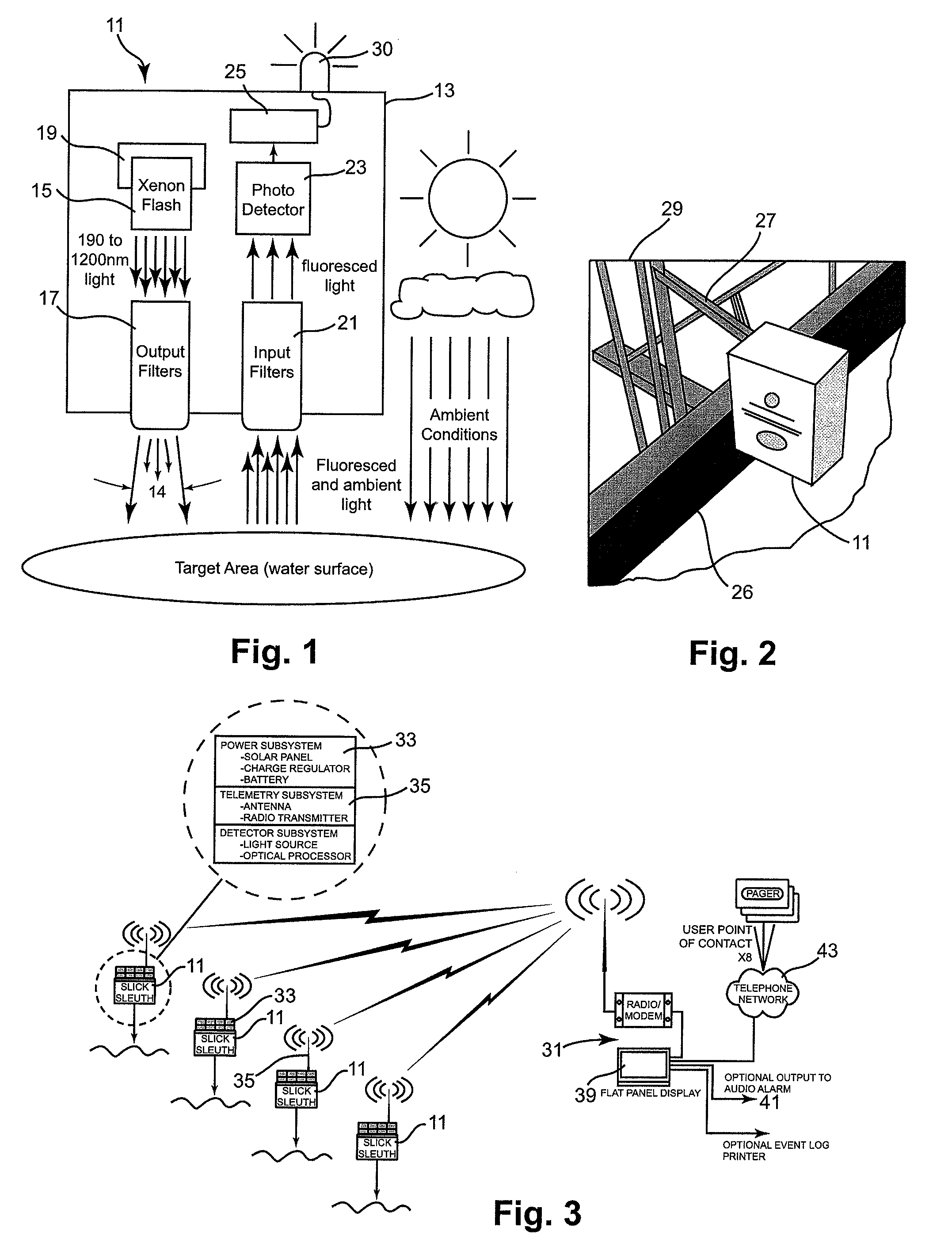
"The invention is a reliable and economical oil detection system that can detect small amounts of petroleum on water surfaces or in water near the surface. It uses a special optical sensor that is installed above the surface to provide clearance between it and the surface. The system can operate at a distance of up to 5 meters above the surface and is suitable for monitoring spills and leakages from land-based installations and in high-velocity water movements. It uses a high-power lamp and filters to focus pulsed light onto the target area and detects the fluorescing light emanating from any hydrocarbon present. The system is designed to recognize a target set of hydrocarbons while minimizing background interference."

Problems solved by technology

Oil spills and leakages, both large and small, have become a major problem throughout the world.
Previous in-water systems which were developed for monitoring bodies of water have required substantial maintenance as they were susceptible to bio-fouling and to debris inherent within water deployment.
Likewise, flow-through systems were found to be susceptible to bio-fouling and oil staining on the sampling tube.

Method used


Image

  • Non-contact oil spill detection apparatus and method
  • Non-contact oil spill detection apparatus and method
  • Non-contact oil spill detection apparatus and method

Examples


Embodiment Construction

[0012]Oils and other organic compounds are known to fluoresce; thus, effective detection apparatus can be used to detect the presence of oil by appropriately exciting a floating oil film and measuring resultant fluorescence. Fluorescence is an optical phenomenon which occurs when a compound absorbs light at one wavelength and then emits light at a longer wavelength. When fluorescent compounds are bombarded with light, some of the light energy is absorbed through the excitation of electrons to higher energy states. Once the light source is removed, the excited electrons fall back to their ground state giving off light in the process. This process is very similar to what makes glow-in-the-dark materials possible, except it takes place in a much shorter period of time. Because some energy is lost as heat in the absorption-emission process, the wavelength of the emitted light is always longer than the wavelength of the absorbed light. Typically the absorbed light for hydrocarbons is in ...


PUM

PropertyMeasurementUnit
apex angleaaaaaaaaaa
wavelengthsaaaaaaaaaa

Abstract

Apparatus for detecting the presence of a targeted group of hydrocarbons, such as diesel / fuel oil, lube oil, motor oil, hydraulic oil, jet fuel, mineral oil and crude oil in a highly reliable manner even though present at only extremely low concentration. A high power, pulsed light source is focused into a collimated beam that is reduced by a set of filters to a band of pulsed light within a precise set of wavelengths and directed vertically onto a target surface, such as a body of water. All but a precise band of light wavelengths returning to the apparatus are blocked so that substantially all light which then reaches an internal photodetector is within such precise band of wavelengths; as a result receipt of such light programmed intervals following such pulses is indicative of the presence of a member of the targeted hydrocarbon group.

Description

[0001]This application claims priority from U.S. Provisional Application Ser. No. 60 / 780,976, filed Mar. 10, 2006.[0002]The invention relates to an apparatus and a method for detecting spilled or leaking pollutants, more particularly to such apparatus and methods that use monitors mounted above a target surface and effect non-contact monitoring to detect the presence of hydrocarbons or other organic contaminants that may be present, and still more particularly to systems and methods designed to monitor the surface of a body of water to detect hydrocarbons that may be floating on the water surface.BACKGROUND OF THE INVENTION[0003]Oil spills and leakages, both large and small, have become a major problem throughout the world. With continued dependence on fossil fuels and oil derivative products, there is more production, transportation, storage, and use of oils than ever before. Because oil spill and leakage prevention and response are growing concerns as a result of growth, demand, a...

Claims


Application Information

Patent Timeline
Patent Type & Authority Patents(United States)
IPC IPC(8): G01N33/28
CPCG01J3/02G01J3/0264G01J3/0283G01J3/0291G01J3/10G01J3/4406G01N21/64G01N33/1833G01N2021/1793G01N2021/6471G01N2201/0212
Inventor PEARLMAN, MICHAEL D.
Owner INTEROCEAN SYST LLC
Learn More