Provider link state bridging

a technology of provider link state and routing protocol, applied in the field of Ethernet traffic routing protocols, can solve the problems of network congestion, unusable network capacity, and inability to exploit the breadth of connectivity in the mesh network at any given instant in time, so as to reduce the possibility of unbounded replication, minimize traffic impact, and improve link utilization efficiency

Inactive Publication Date: 2010-03-30
RPX CLEARINGHOUSE
View PDF3 Cites 52 Cited by
  • Summary
  • Abstract
  • Description
  • Claims
  • Application Information

AI Technical Summary

Benefits of technology

[0013]Bridges exchange state information by a link state protocol and maintain a state database utilized to determine shortest paths between peer bridges by a shortest path algorithm. Under conditions of Equal Cost Multiple Paths between any two bridges, a consistent choice of path is made by all bridges, such that “go” and “return” unicast paths and the relevant segments of the two multicast trees are co-routed. The forwarding tables or forwarding information base (FIB) is them populated with appropriate unicast and multicast addresses. Unique unicast and multicast distribution trees are then created at each bridge providing more efficient link utilization.
[0014]Loop suppression is provided by a reverse path forwarding check performed on received packets at each bridge. The RPFC determines if the packet has arrived on the correct port or interface as identified in the FIB, packets that do not arrive on the correct port are discarded. This is possible because of the co-routed property of all paths between any two points (as above). During time of network instability, such as during a bridge or link failure where looping may potentially occur and the network topology is not converged, RPFC may be disabled for unicast packets to minimize the impact on traffic. When the topology re-converges at each bridge RPFC can be re-enabled. For multicast traffic the RPFC is never disabled to reduce the possibility of unbounded replication.

Problems solved by technology

However the Ethernet paradigm of flooding and learning means that typically the breadth of connectivity that exists in a mesh network cannot be exploited at any given instant in time due to the requirement to ensure that no replicating path can loop.
However, if the packet were to be sent on multiple routes simultaneously, network congestion would increase and possible looping conditions may result.
If the bridges in the loop flood, or the packet is a multicast packet, additional copies of the packet will be generated in each traversal of the loop, a highly undesirable outcome.
However the simplistic approach to loop-free connectivity can result in an excess of un-used network capacity due to the requirement to prune the physical topology to a single loop-free spanning tree.
Using STP in an Ethernet network limits the utilization efficiency of thee links or LAN segments in the network.
In a small LAN environment this may not be an issue, however in a WAN or provider network unused capacity both impacts scaling and represents under utilized investment.
In addition when a failure does occur, the performance of the whole network is impacted during the time required to re-converge STP and stabilize all the bridges in the network.
However fundamental data plane modifications are required to implement these solutions which limits their utility.
In addition, only limiting the number of times a packet may replicate is a demonstrably incomplete solution to the looping problem.

Method used


Image

  • Provider link state bridging
  • Provider link state bridging
  • Provider link state bridging

Examples


Embodiment Construction

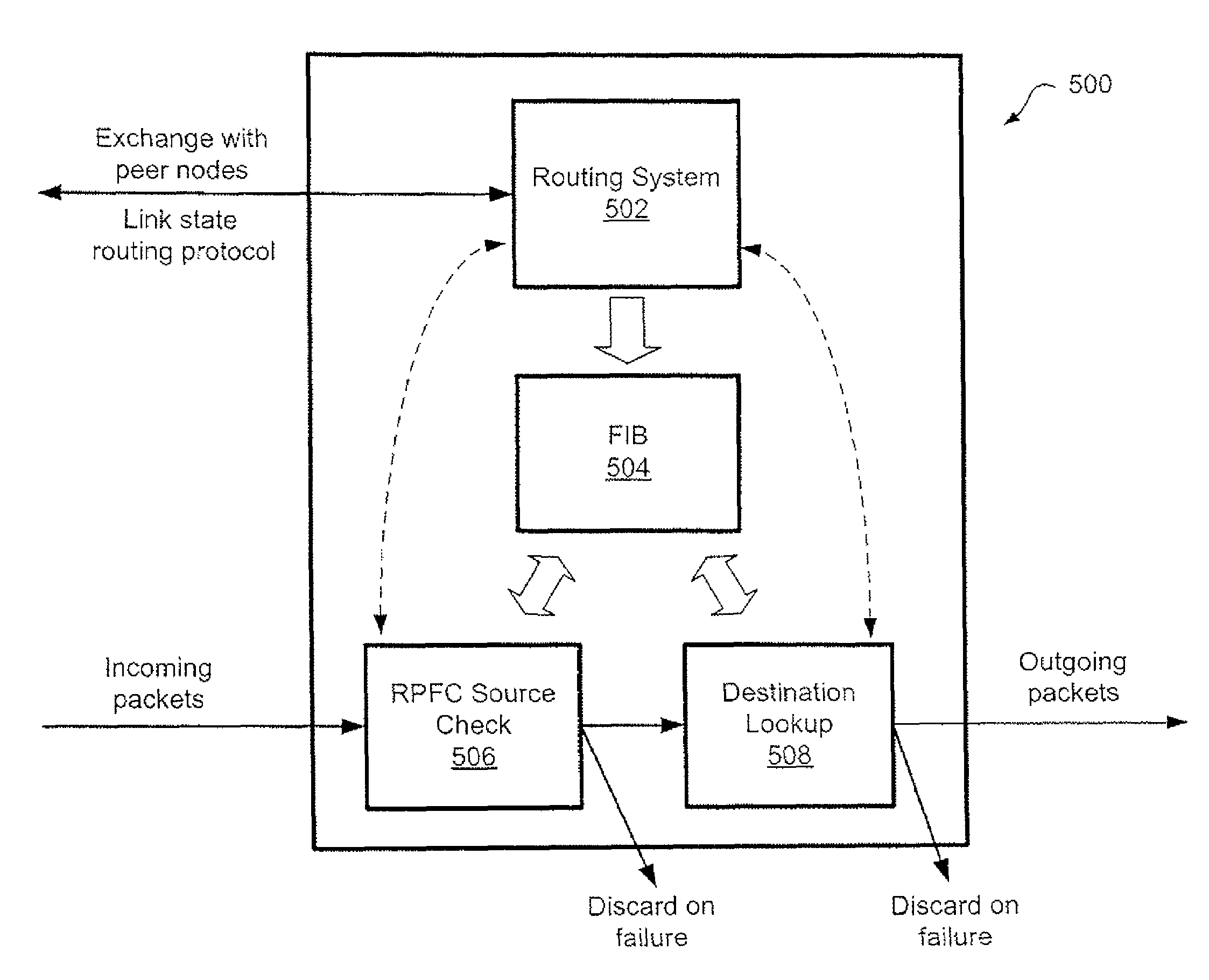
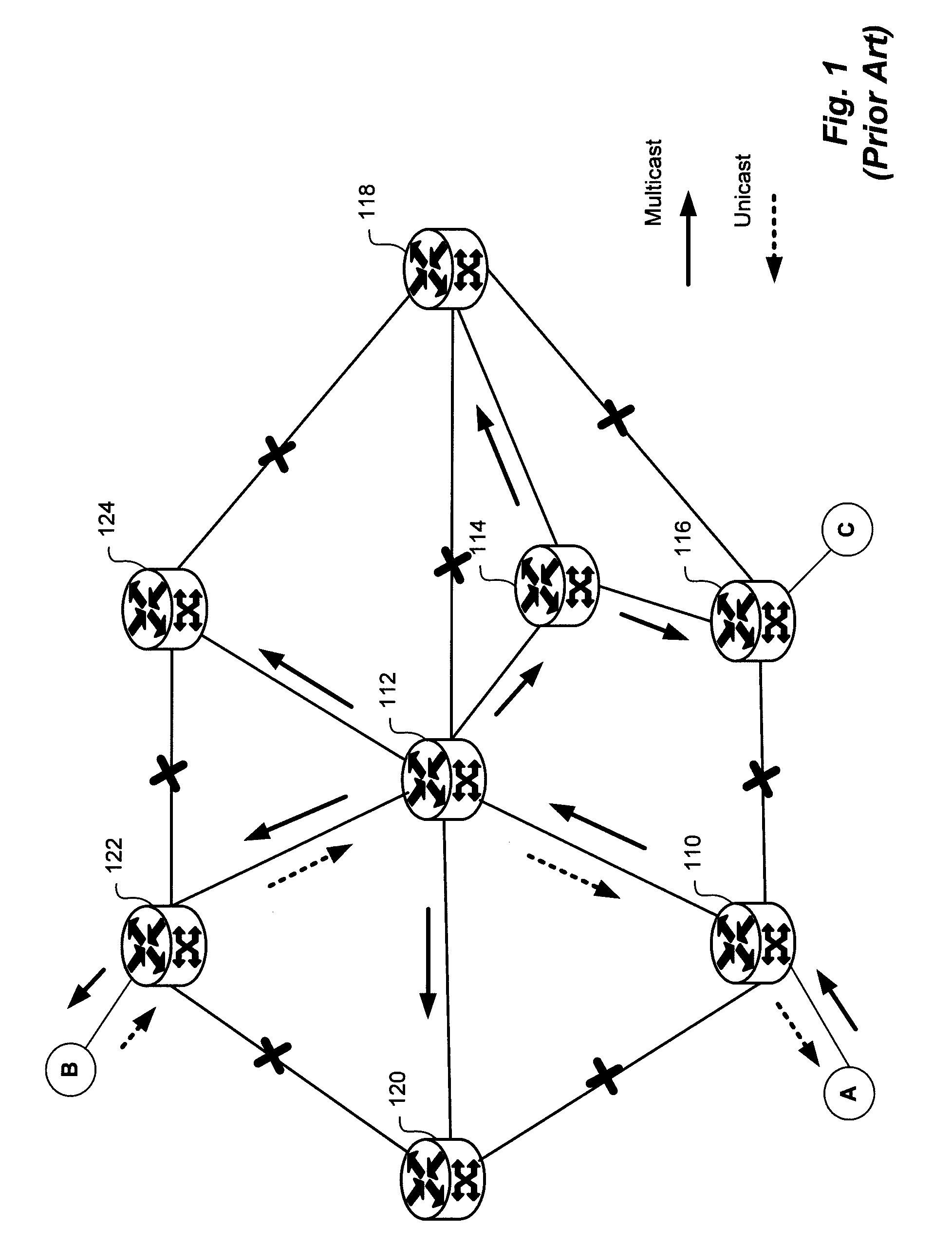
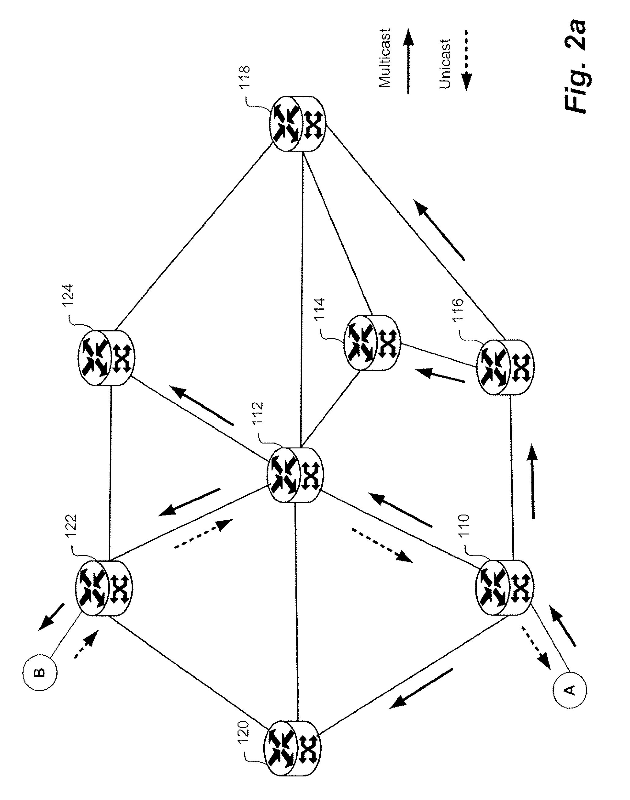
[0033]Embodiments of the present invention are described below, by way of example only, with reference to FIGS. 2-9. The present invention provides a system, method and device for loop-free Ethernet networking.

[0034]Provider Link State Bridging (PLSB) enables Ethernet networks to be scaled from the LAN space to the WAN or provider network space by providing more efficient use of network capacity with loop-free shortest path forwarding. Rather than utilizing a learned network view at each node by using the Spanning Tree Protocol (STP) algorithm combined with transparent bridging, in a PLSB based network the bridges forming the mesh network have a synchronized view of the network topology. This is achieved via the well understood mechanism of a link state routing system. The bridges in the network have a synchronized view of the network topology, have knowledge of the requisite unicast and multicast connectivity, can compute a shortest path connectivity between any pair of bridges in ...


PUM


Abstract

Provider Link State Bridging (PLSB) expands static configuration of Ethernet MAC forwarding tables by the control plane and utilizes direct manipulation of Ethernet forwarding by a link state routing system. At least one media-access-control (MAC) address for unicast forwarding to the bridge and at least one MAC address for multicast forwarding from the bridge are assigned. Bridges exchange state information by a link state bridging protocol so that a synchronized configured view of the network is shared between nodes. Each node can calculate shortest path connective between peer bridging nodes and populated the appropriate forwarding tables. A reverse path forwarding check is performed on incoming packets to provide loop suppression. During times of network instability the loop suppression can be disabled for unicast packets as identified by the destination MAC address to buffer packets and minimize the impact on traffic flow.

Description

CROSS-REFERENCE TO RELATED APPLICATIONS[0001]This application claims priority of U.S. Provisional Patent Application Ser. No. 60 / 723,479 filed Oct. 5, 2005, U.S. Provisional Patent Application Ser. No. 60 / 735,884 filed Nov. 14, 2005 and U.S. Provisional Patent Application Ser. No. 60 / 745,330 filed Apr. 21, 2006. Each of the above applications is incorporated herein by reference.TECHNICAL FIELD[0002]The present invention relates to Ethernet traffic routing protocols, and in particular to configuring connectivity in a meshed Ethernet network.BACKGROUND[0003]In Ethernet network architectures devices connected to the network compete for the ability to use the shared telecommunications path at any given time. Where multiple bridges or nodes are used to interconnect network segments, multiple potential paths to the same destination will exist in a meshed network architecture. The benefit of this architecture is that it provides path redundancy between bridges and permits capacity to be ad...

Claims


Application Information

Patent Timeline
Patent Type & Authority Patents(United States)
IPC IPC(8): H04L12/28H04L45/02H04L45/16H04L45/18H04L49/111
CPCH04L12/462H04L12/18H04L12/4641H04L12/4675H04L45/00H04L45/02H04L45/12H04L45/16H04L45/18H04L45/48H04L45/66H04L49/354H04L12/4625H04L41/0816H04L49/3009H04L45/03H04L45/484H04L12/28
Inventor ALLAN, DAVIDBRAGG, NIGEL
Owner RPX CLEARINGHOUSE
Why Eureka
Try Eureka