Electromechanical cylinder lock

a technology of electromechanical and cylinder locks, which is applied in the direction of cylinder locks, carpet fasteners, locks, etc., can solve the problems of prior art systems that do not provide the ability to retrofit a purely mechanical lock to form, and prior art systems using electromagnetic components such as solenoids have been found to be impractical, and achieve the effect of greater flexibility

Inactive Publication Date: 2010-04-06
ASSA ABLOY HIGH SECURITY GRP INC
View PDF11 Cites 56 Cited by
  • Summary
  • Abstract
  • Description
  • Claims
  • Application Information

AI Technical Summary

Benefits of technology

[0011]An important benefit of the invention resides in the fact that the side bar, slider bar and electrically powered actuator device are entirely (or substantially entirely) contained within the barrel. This permits the entire barrel to be removed and placed in the outer shells of different lock cylinders. The invention permits the barrel to be substituted for the barrel of a purely mechanical cylinder lock to retrofit the lock into an electromechanical lock system. In addition, the invention contemplates utilizing different but interchangeable electromechanical barrels with a plurality of lock cylinders in a lock system. Moreover, the compact, removable barrel may carry some or all of the electronic hardware, firmware and / or software associated with the lock to provide even greater flexibility in various applications.
[0012]According to another aspect of the present invention, a thermal interlock mechanism is provided to prevent attempts at circumventing a heat-actuated lock release through external heating of the lock, by disabling the lock upon such external heating.

Problems solved by technology

Despite progress made in the development of prior art electromechanical locking systems, several deficiencies exist which leave room for improvement.
For example, prior art systems do not provide the ability to retrofit a purely mechanical lock to form an electromechanical lock which is operated at least in part by information stored in a key and / or lock cylinder.
Additionally, prior art systems using electromagnetic components such as solenoids have been found to be impractical, because of the small space available and the relatively large size of components needed to develop enough force to release the blocking mechanism.

Method used


Image

  • Electromechanical cylinder lock
  • Electromechanical cylinder lock
  • Electromechanical cylinder lock

Examples


Embodiment Construction

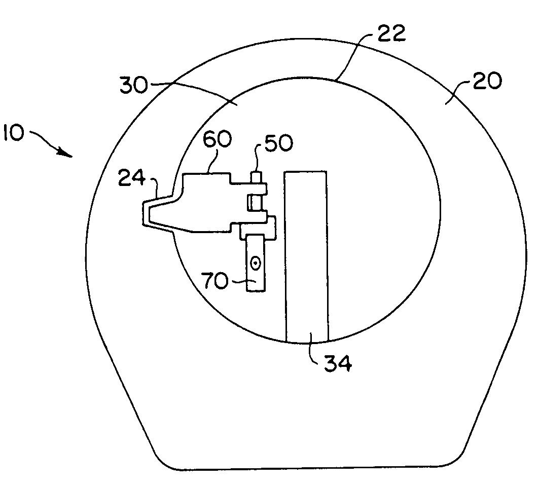
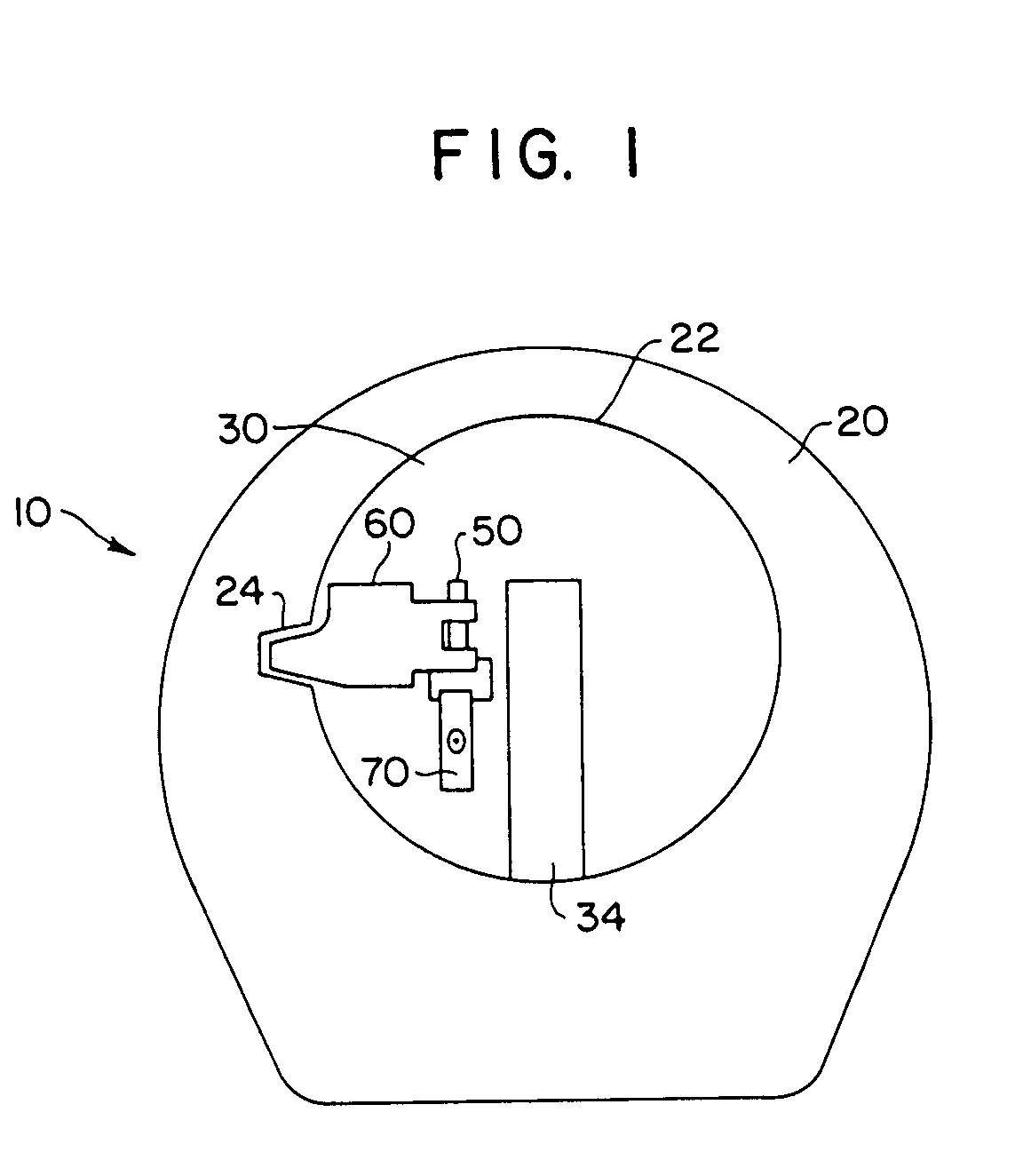
[0026]With reference to FIG. 1, a first embodiment of the present invention is indicated generally by the reference numeral 10 and includes a cylinder or outer shell 20 having a bore 22 in which is positioned a rotatable barrel or plug 30. The barrel 30 has an outer surface substantially corresponding to the bore 22 of the shell and includes a keyway 34 configured to receive a key as is known in the art. The barrel 30 includes a plurality of tumbler pin bores which receive tumbler pins (not shown) as is known in the art. The manner in which a properly bitted key (not shown) engages the tumbler pins and positions them at a shear line to permit the barrel 30 to be rotated with respect to the shell 20 is known in the art and thus will not be described in any great detail herein. However, it should be noted that the tumbler pins may be simply lifted by the bitting surfaces on the key, or they may be lifted rotatively by a key including skew cut bitting surfaces, such as that used with a...


PUM


Abstract

An electromechanical cylinder lock includes an outer lock shell and a rotatable lock barrel located therein which is controlled by dual locking features. A side bar or fence selectively blocks and permits rotation of the barrel with respect to the shell in response to insertion of a key into a keyway in the barrel. A slider bar is movable between a blocking position in which the side bar is prevented from permitting rotation of the barrel, and an unblocking position in which the side bar permits rotation of the barrel. Alternately, a blocking mechanism is provided to block motion of tumbler pins in the cylinder lock. A shape memory alloy actuator, such as a wire made of NITINOL disposed in the barrel is activated by an electric current in response to determination by an electronic control device whether an attempt to open the lock is authorized. Thermal interlock protection from external heating of the lock is also provided.

Description

BACKGROUND OF THE INVENTION[0001]1. Field of the Invention[0002]The present invention relates generally to an electromechanical cylinder lock and, in particular, to a cylinder lock in which an electrical actuator is employed to provide access to the lock cylinder.[0003]2. Description of Related Art[0004]Electromechanical locking devices are known which include electrically interfaced or controlled release mechanisms for operating a lock cylinder. For example, U.S. Pat. No. 4,712,398 discloses an electronic locking system comprising a lock cylinder with a rotatable plug located therein. An electronically activated release assembly is provided which selectively disengages a locking pin from the plug to allow turning of the key to rotate the plug relative to the cylinder. The lock cylinder and key each include an electronic memory device containing keying system codes. Upon insertion of the key the release mechanism disengages the locking pin from the plug to allow its rotation. U.S. P...

Claims


Application Information

Patent Timeline
Patent Type & Authority Patents(United States)
IPC IPC(8): E05B47/06E05B47/00
CPCE05B47/0009E05B47/063E05B51/005F16C2202/28Y10S292/66Y10T70/20Y10T70/7079Y10T70/7119Y10T70/713Y10T70/7616Y10T70/7667Y10T70/7684
Inventor FIELD, PETERKERR, DUNCAN
Owner ASSA ABLOY HIGH SECURITY GRP INC
Why Eureka
Try Eureka