Transporting and storing curved wind turbine blades

a technology of wind turbine blades and curved blades, which is applied in the direction of wind motors with parallel air flow, transportation items, wind energy generation, etc., can solve the problems of not being able to transport curved blades under bridges and tunnels, and achieve the effect of facilitating the storage and transportation of curved blades

Active Publication Date: 2010-04-06
LM GLASSFIBER
View PDF3 Cites 33 Cited by
  • Summary
  • Abstract
  • Description
  • Claims
  • Application Information

AI Technical Summary

Benefits of technology

[0008]According to a first aspect, the object of the invention is to provide a method of facilitating the storage and transportation of a curved blade for a wind turbine without the storage or the transportation being considerably impeded by the shape of the blade.
[0009]The object of the invention is obtained by a method where the blade is prestressed by means of prestressing means at a distance from the blade root in such a manner that the blade tip is brought closer to the longitudinal central axis of the blade root. The longitudinal central axis of the blade root should be interpreted as a straight line extending through the centre of the blade root and perpendicular to the plane of the root flange. As a result, the blade may be arranged in a less curved shape, thereby facilitating storage and transportation. Usually, modern wind turbine blades are transported by truck or ship across great distances. When these blades curve heavily, they may cover the entire width of the road or more when the blade is arranged so that the curvature extends in a horizontal plane. When the blade is arranged in such a manner that the curvature extends in the vertical plane, it is often not possible to transport it under bridges, through tunnels and the like. By “straightening” out the blade by the method according to the invention, the blade is arranged in a shape allowing for transportation by truck by relatively narrow roads and under bridges, through tunnels and the like. Curved blades have hitherto been provided with smaller curvatures than desired to avoid the above disadvantages. The longer the blade, the smaller the relative curvature, which is undesirable as long blades have large deflections in high wind.
[0010]According to a preferred embodiment, the blade is prestressed so heavily that the distance between the blade tip and the longitudinal central axis of the blade root does not exceed twice the radius of the blade root, more preferably not exceeding the radius of the blade root. In this way, the blade obtains a shape substantially taking up the same space as a non-curved blade of the same size.
[0019]In a preferred embodiment, the rigid latticework includes a substantially plane bottom wall and two flange walls, said flange walls substantially being rectilinear and following the outer outline of the blade. The counterpart may advantageously be adapted such that the flange walls are hinged or removably fastened to the bottom wall, thereby allowing said flange walls to be folded down during the transport of the empty counterpart.
[0020]Both a resilient and a rigid counterpart may be shaped or have abutment members shaped to allow the blade to abut the counterpart leniently without damaging the surface of the blade.
[0021]According to an embodiment, the resilient counterpart may be formed of a second curved wind turbine blade upended in relation to the first blade, whereby the roots of the two blades are secured in respective first frames, and whereby the tips of the two blades are secured in respective second frames, and where said first frame of said first blade and said second frame of said second blade are secured to each other and where said second frame of said first blade and said first frame of said second blade are subsequently forced towards each other and secured to each other. As a result, the blades may be stored and transported two by two in a very simple and compact way.

Problems solved by technology

When the blade is arranged in such a manner that the curvature extends in the vertical plane, it is often not possible to transport it under bridges, through tunnels and the like.
The longer the blade, the smaller the relative curvature, which is undesirable as long blades have large deflections in high wind.

Method used


Image

  • Transporting and storing curved wind turbine blades
  • Transporting and storing curved wind turbine blades
  • Transporting and storing curved wind turbine blades

Examples


Embodiment Construction

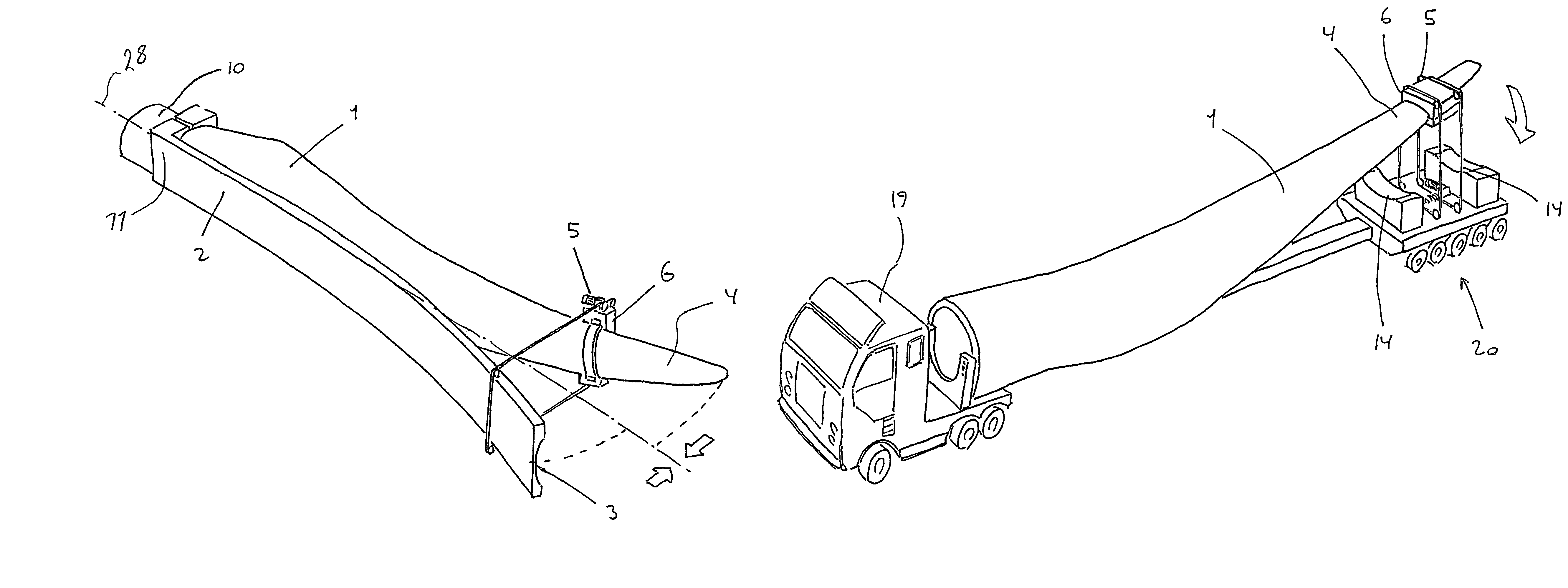
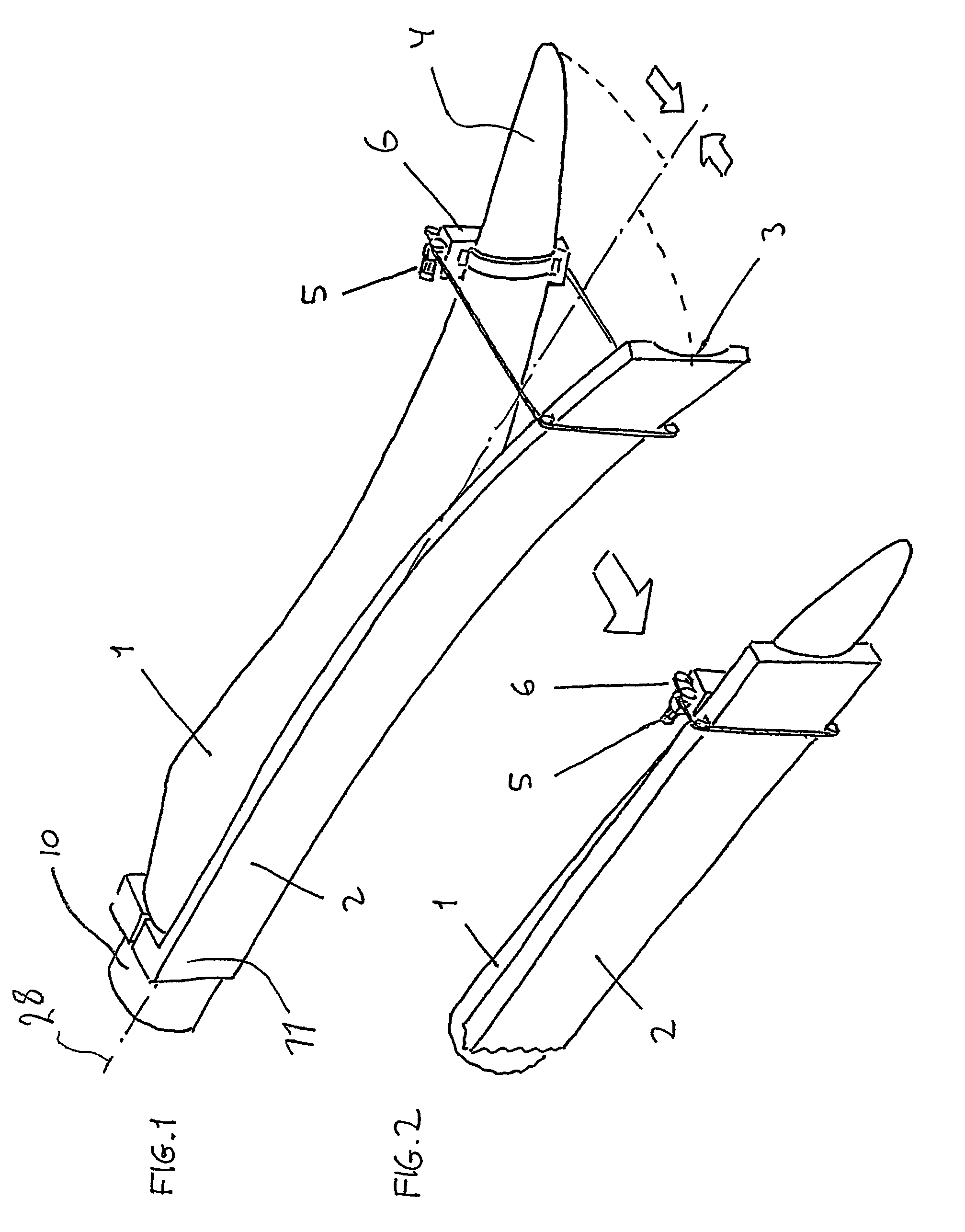
[0055]FIG. 1 shows a resilient curved blade 1 mounted on a resilient counterpart 2 having an inner outline 3 adapted to the outer outline of the blade. The resilient counterpart is secured to the blade 1 at the root 10 thereof by means of root fittings 11 receiving the cylindrical outline of the root 10. At the outermost portion of the counterpart 2 and the blade 1, a winch arrangement 5 is mounted by which the blade 1 and the counterpart 2 may be pulled towards each other and thereby straightened out, as shown in FIG. 2. The winch arrangement 5 shown may be removable and thereby mobile such that it may be used for prestressing several blades 1 for the same transport or storage. At delivery, the winch arrangement 5 may also be included and used for unpacking the prestressed blades 1. The longitudinal central axis of the blade root has been denoted by the reference numeral 28.

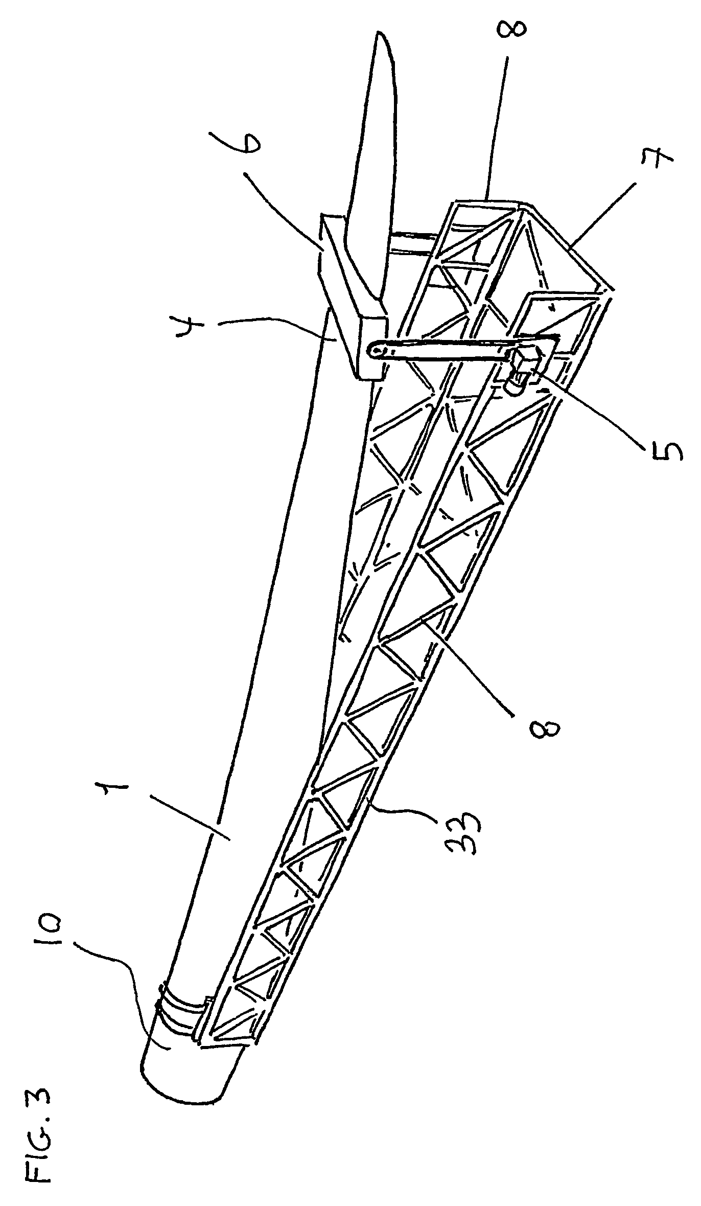
[0056]FIG. 3 shows a counterpart 33 structured as a rigid latticework which, in principle, is used in same wa...


PUM


Abstract

A method of transporting and storing a wind turbine blade includes providing a wind turbine blade including a blade root having a longitudinal central axis and a blade tip. The wind turbine blade curves in an unloaded state in such a manner that the blade presents a substantially concave face and a substantially convex face, and such that the blade tip is spaced apart from the longitudinal central axis of the blade root. The wind turbine blade is prestressed at a distance from the blade root in such a manner that the blade tip is brought closer to the longitudinal central axis of the blade root.

Description

TECHNICAL FIELD[0001]The invention relates to the transportation and storing of a wind turbine blade including a blade root and a blade tip, where the wind turbine blade curves in the unloaded state in such a manner that the wind turbine blade presents a substantially concave face and a substantially convex face, and such that said blade tip is spaced apart from the longitudinal central axis of said blade root. The invention further relates to a wind turbine blade of the above type as well as an apparatus for transporting and storing a wind turbine blade of the above type.BACKGROUND ART[0002]It is commonly known to transport fibre-reinforced polymer blades for modern wind turbines generating electricity by truck, by train or by ship. In order to include as many blades as possible at each transport, the blades are often packed upended in relation to each other. For example, three blades are often packed so that two roots are arranged at the one end interspaced by one blade tip, thus ...

Claims


Application Information

Patent Timeline
Patent Type & Authority Patents(United States)
IPC IPC(8): B60P7/08B60P3/40F03D1/00F03D1/06
CPCB60P3/40F03D1/0633F03D1/005B65D2585/6897Y02E10/721F03D13/40Y02E10/72
Inventor GRABAU, PETER
Owner LM GLASSFIBER
Why Eureka
Try Eureka