Manufacturing machine for manufacturing heat-source rod and method of manufacturing same

a manufacturing machine and heat source chip technology, applied in tobacco treatment, non-fibrous pulp addition, tobacco, etc., can solve the problems of defective heat source chip with insufficient bonding between the fuel core and the heat source chip, inability to effectively function as an adhesive, and inability to integrate substitute smoking articles with such heat source chips. , to achieve the effect of convenient connection and easy formation

Inactive Publication Date: 2010-04-06
JAPAN TOBACCO INC
View PDF16 Cites 103 Cited by
  • Summary
  • Abstract
  • Description
  • Claims
  • Application Information

AI Technical Summary

Benefits of technology

[0013]The wet band of the heat-insulating web dissolves the binder contained in the heat-insulating web, thereby forming an adhesive for bonding the extrusion-molded article, or in other words, a streak-like adhesive region. When the extrusion-molded article is wrapped in the heat-insulating web so that the fuel rod is formed, the streak-like adhesive region bonds the extrusion-molded article and the heat-insulating web together. The wet band, namely the streak-like adhesive region extends circumferentially relative to the extrusion-molded article, crossing the axial grooves of the extrusion-molded article, and therefore securely bonds the extrusion-molded article and the heat-insulating web together and increases the bonding strength between them. This allows the wet band to be formed with a small amount of the solvent. Thus, the hardness of the outer surface of the extrusion-molded article is sufficiently maintained, which ensures that the heat-source chip obtained from the heat-source rod has burning characteristics required.
[0017]The waveform wet band is easily formed by combining the traveling of the heat-insulating web and the vibration of the vibrating member. The use of the flexible nozzle facilitates the connection between a pipe extending from the solvent supply source and the flexible nozzle.

Problems solved by technology

In this case, the glue rail is not in contact with the cylindrical surface of the extrusion-molded article and therefore does not effectively function as an adhesive for bonding the extrusion-molded article and the heat-insulating web together.
If a heat-source chip is obtained from a heat-source rod manufactured this way, the heat-source chip is defective with insufficient bonding between the fuel core and the heat-insulating sheath, and a substitute smoking article with such heat-source chip incorporated is also defective.
If a shock is applied to such defective substitute smoking article in the axial direction during transportation or when it is held in a consumer's hand, the shock may cause axial shift of the fuel core of the heat-source chip.
Such protrusion or plunge of the fuel core makes the smoking of the substitute smoking article difficult.
In either case, however, a large amount of water is applied onto the heat-insulating web, so that an increased amount of water penetrates into the cylindrical surface of the extrusion-molded article, which decreases the hardness of the outer surface of the extrusion-molded article to a great degree.
When fed to the wrapping section, the extrusion-molded article is still in a wet and soft state and therefore contains a large amount of water.
If, in addition to this water contained, a large amount of water penetrates into the extrusion-molded article from the heat-insulating web, the extrusion-molded article cannot maintain the external shape thereof.
Thus, when the extrusion-molded article is wrapped in the heat-insulating web or when the heat-source rod is cut, the axial grooves of the extrusion-molded article may be deformed, or crushed and blocked.
Deforming or crushing the axial grooves like this reduces the flow-passage cross-sectional area of the axial grooves to a great degree, so that the heat-source chip cannot have burning characteristics required.

Method used


Image

  • Manufacturing machine for manufacturing heat-source rod and method of manufacturing same
  • Manufacturing machine for manufacturing heat-source rod and method of manufacturing same
  • Manufacturing machine for manufacturing heat-source rod and method of manufacturing same

Examples


Embodiment Construction

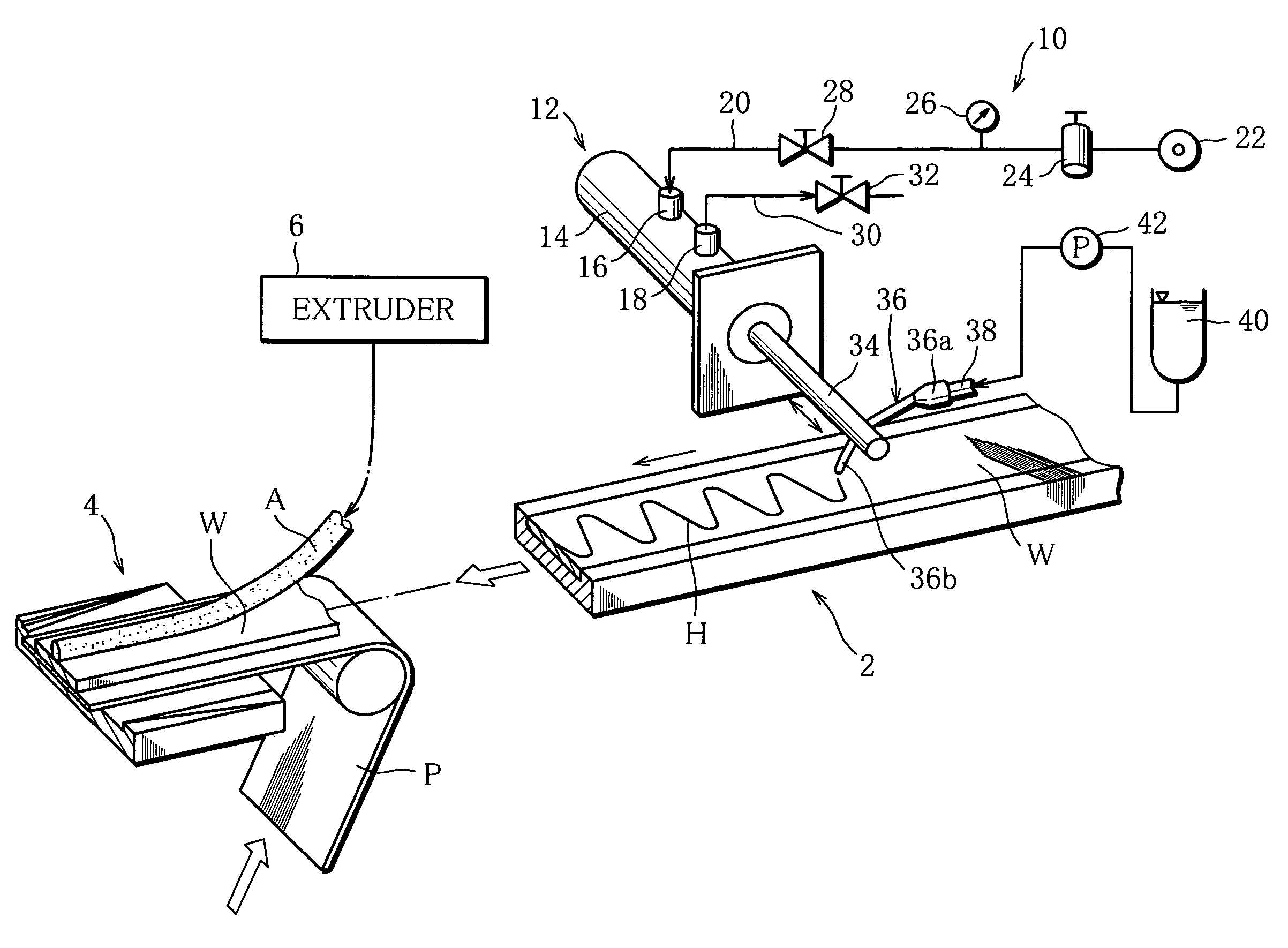
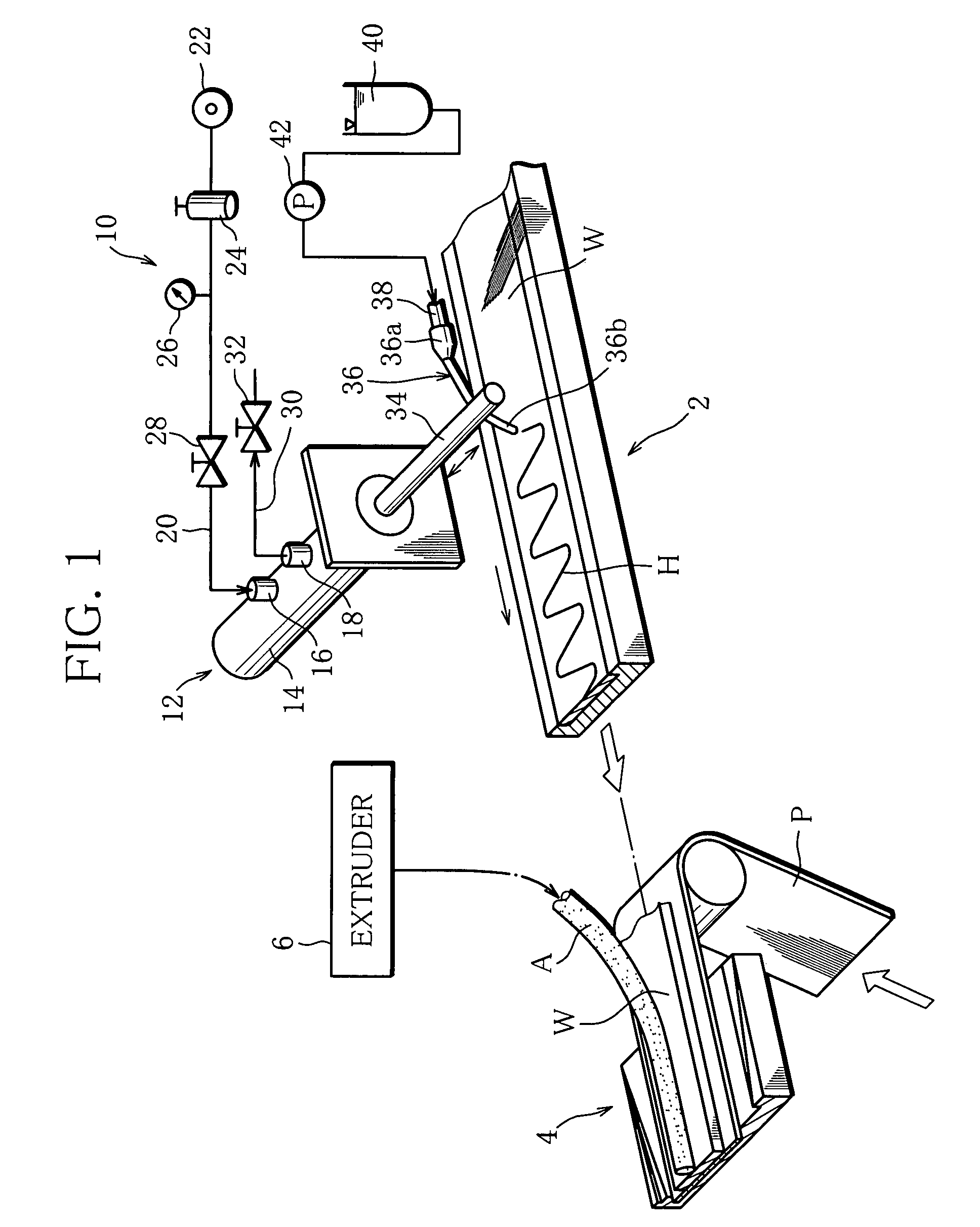
[0031]A manufacturing machine for manufacturing a heat-source rod shown in FIG. 1 has a web path 2. The web path 2 extends to near a wrapping section 4 to feed a heat-insulating web W to the wrapping section 4. The heat-insulating web W is made of unwoven glass-fiber fabric containing a binder such as pectin for binding the glass fiber, and unwound from a web roll (not shown) and fed along the web path 2.

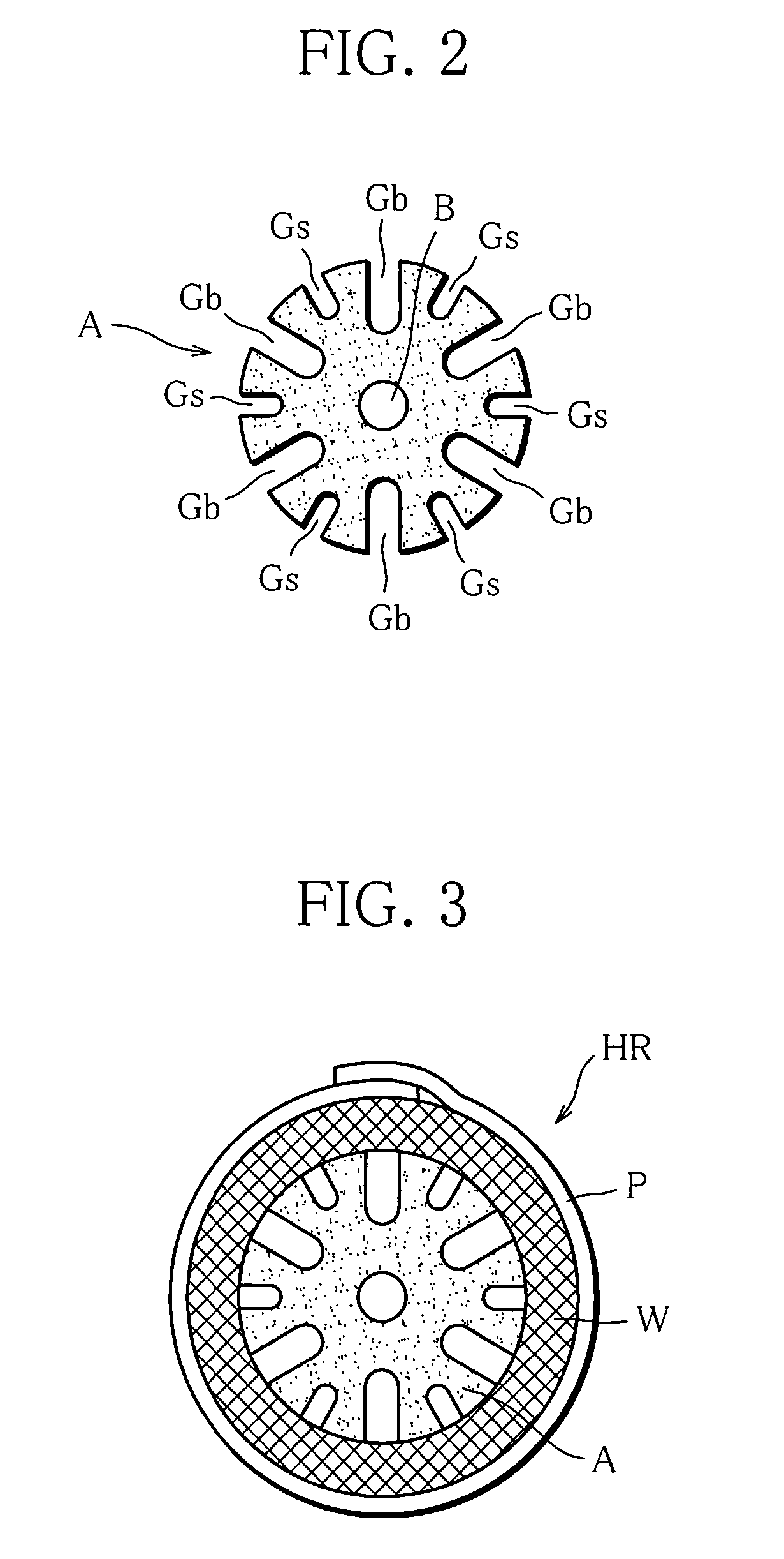
[0032]To the wrapping section 4, a rod-like extrusion-molded article A and a paper web P are fed in addition to the heat-insulating web W. At an inlet end of the wrapping section 4, the heat-insulating web W and the extrusion-molded article A are laid on the paper web P in this order.

[0033]The extrusion-molded article A is molded from a combustible mixture by an extruder 6, and fed to the wrapping section 4 along a predetermined guide path. Specifically, the mixture comprises carbon powder as a fuel, a combustion regulator, tobacco powder, a binder, water, etc., and obtained by mixi...


PUM

PropertyMeasurementUnit
diameteraaaaaaaaaa
inner diameteraaaaaaaaaa

Abstract

A manufacturing machine manufactures a heat-source rod having a rod-like extrusion-molded article made from a combustible material with axial grooves in the cylindrical surface thereof and a heat-insulating web enveloping the article, and is provided with a apparatus 10 for spouting water to the web W in the process of the web W being fed to a wrapping section 4. The spout apparatus 10 includes an air vibrator 12 with a vibrating rod 34, and a flexible nozzle 36 attached to the rod 34 to extend across the rod 34 and supplied with water from a rate regulating pump 42. While the web W is being fed, the end of the nozzle 36 spouts water to the web W, reciprocating widthways relative to the web W due to vibration of the rod 34, and the water spouted dissolves a binder used in the web W to bind heat-insulating fiber, thereby forming a wet band H, where the wet band H has a waveform continuing along the longitudinal direction of the web W and provides a adhesive region for bonding the article.

Description

[0001]This application is a Continuation of copending PCT International Application No. PCT / JP2005 / 019015 filed on Oct. 17, 2005, which designated the United States, and on which priority is claimed under 35 U.S.C. §120. This application also claims priority under 35 U.S.C. §119(a) on Patent Application No(s). 2004-309743 filed in Japan on Oct. 25, 2004. The entire contents of each of the above documents is hereby incorporated by reference.TECHNICAL FIELD[0002]This invention relates to a manufacturing machine for manufacturing a heat-source rod for a heat-source chip, namely, a heat-source rod for obtaining a heat-source chip for use in a smoking article substituting for a cigarette, and a method of manufacturing the same.BACKGROUND ART[0003]The heat-source chip as mentioned above is obtained by cutting a continuous heat-source rod into a specified length. As shown in the specification of Japanese Patent No. 3472591, for example, the heat-source rod comprises an extrusion-molded art...

Claims


Application Information

Patent Timeline
Patent Type & Authority Patents(United States)
IPC IPC(8): H05B3/34A24D1/02A24C5/00A24D1/22
CPCA24B15/165B29C47/0016A24F47/004B29C47/00B29C48/00B29C48/06A24C5/00A24D1/22A24B15/00
Inventor BABA, YASUOOHINATA, HAJIMEHOSOYA, NOBUOYANAGI, TOSHIO
Owner JAPAN TOBACCO INC
Why Eureka
Try Eureka