
Optical OFDM transmission with improved efficiency

a transmission efficiency and optical technology, applied in the field of optical communication, can solve the problems of inability to control the system designer's required guard interval, the reduction in transmission efficiency is negligible, and the deployment of ofdm within optical systems may not be easy to achiev

Inactive Publication Date: 2010-04-06
OFIDIUM PTY LTD
View PDF3 Cites 57 Cited by
  • Summary
  • Abstract
  • Description
  • Claims
  • Application Information

AI Technical Summary

Benefits of technology

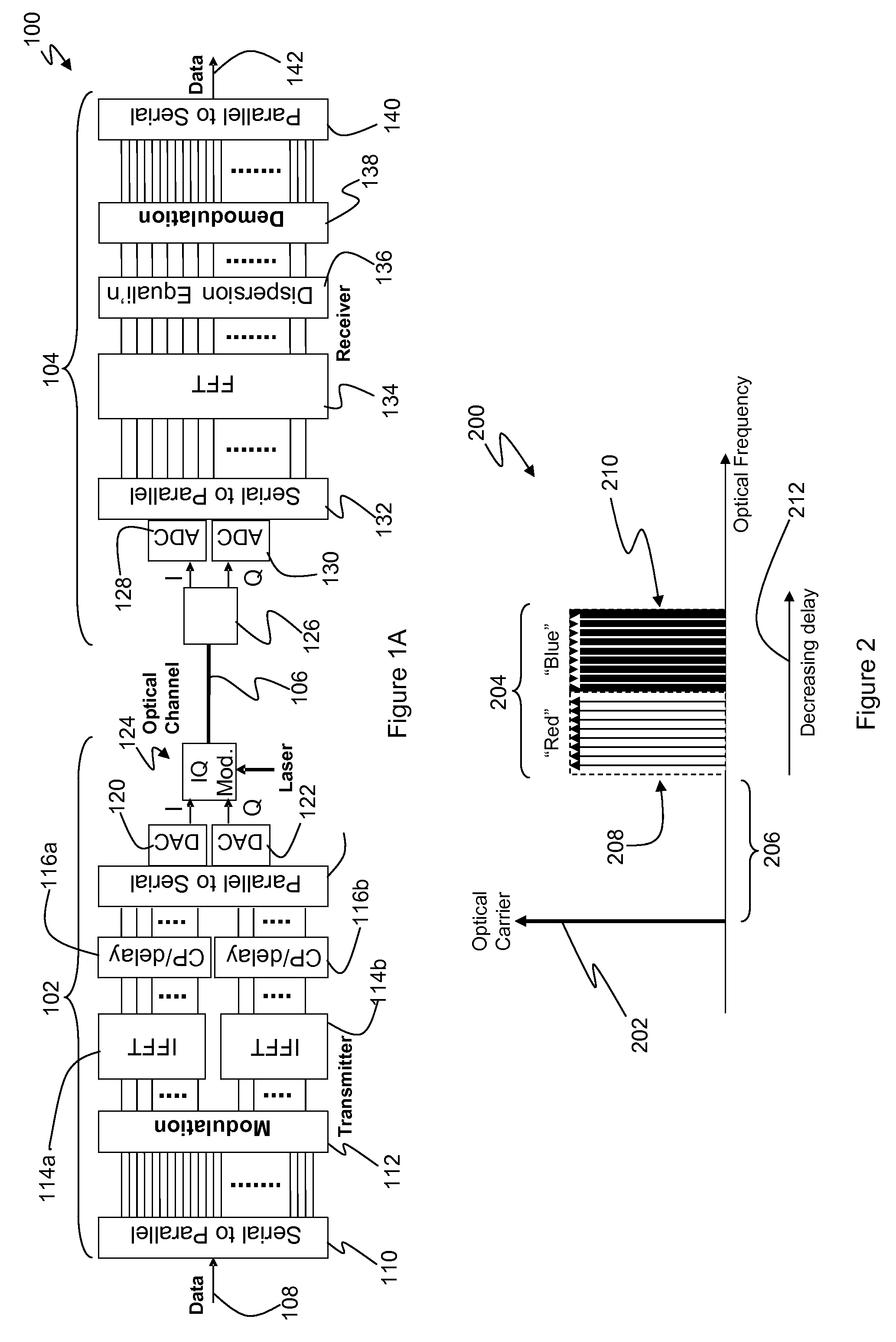
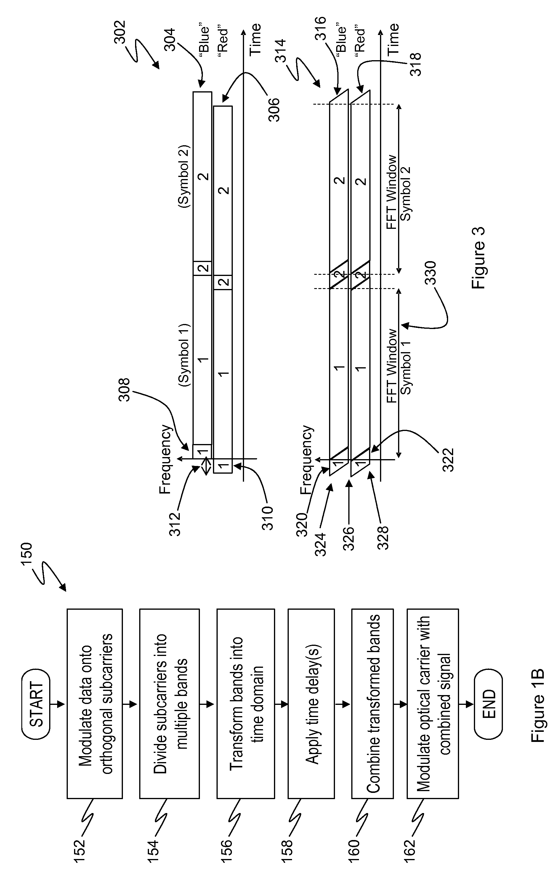
[0016]Advantageously, embodiments of the invention are based upon the recognition by the present inventor that the predictable characteristics of chromatic dispersion in single-mode optical fibres may be utilised to mitigate the effects of inter-symbol interference occurring during transmission through such fibres. In particular, the maximum differential delay between components of a transmitted optical signal under the influence of chromatic dispersion tends to be a monotonically increasing function of the total signal bandwidth. Thus narrowband signals experience lower levels of differential delay, and hence require shorter guard intervals, than wideband signals. The invention is based upon dividing the overall transmitted signal into a plurality of narrower bands, each of which will experience a lower differential delay, and then accounting for the average differences in transmission delay between the various bands by applying corresponding time delays to the transformed bands.
[0018]Preferably, the predetermined duration of the guard interval is greater than the maximum time delay due to dispersion of the optical channel across any of the transmitted frequency bands. Advantageously, this ensures that inter-symbol interference due to chromatic dispersion may be avoided altogether.

Problems solved by technology

So long as the duration of each symbol is long, compared with the guard interval, as is the case in typical wireless transmission systems, the resulting decrease in transmission efficiency is negligible.
However, the deployment of OFDM within optical systems presents new challenges, because the relevant characteristics of typical transmitted optical signals are quite different from those of radio signals, in relation to which OFDM has so far most commonly been employed.
However, since the extent of possible inter-symbol interference, and hence the required guard interval duration, is dependent upon characteristics of the optical channel, the required length of the guard interval may not be within the control of the system designer.
Furthermore, a major source of inter-symbol interference in single-mode optical fibre transmission systems is chromatic dispersion, in accordance with which the differential delay experienced across the transmitted signal spectrum generally increases with increasing signal bandwidth.
Firstly, the size of the FFT implementations used in the transmitter and receiver is necessarily equal to the number of subcarriers, and accordingly increasing the number of subcarriers increases the size of the FFTs required.
This may be particularly disadvantageous in high-capacity transmission systems, wherein the FFTs are likely to be implemented in hardware, and accordingly the required silicon area, and wiring complexity, may be significantly increased.
As noted above, this is incompatible with the use of longer symbols in order to reduce the overhead due to required guard intervals.

Method used


Image

  • Optical OFDM transmission with improved efficiency
  • Optical OFDM transmission with improved efficiency
  • Optical OFDM transmission with improved efficiency

Examples


Embodiment Construction

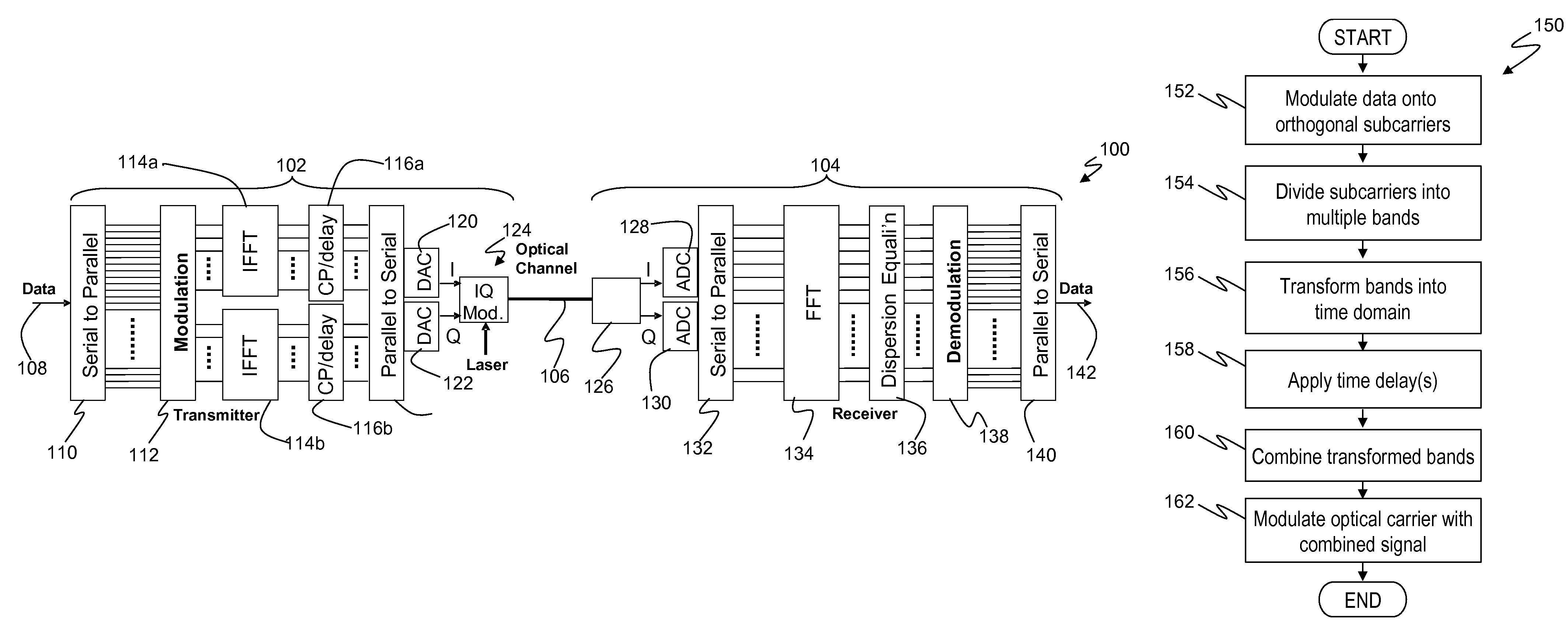
[0037]FIG. 1 illustrates schematically a system 100 for communicating digital information over a dispersive optical channel, according to a preferred embodiment of the present invention. The exemplary system 100 includes transmission apparatus 102 and receiving apparatus 104, which for convenience are more generally referred to herein as the “transmitter” and the “receiver” respectively.

[0038]The transmitter 102 communicates with the receiver 104 via optical channel 106, which generally exhibits linear optical dispersion, including chromatic dispersion and polarisation mode dispersion. The optical channel 106 may also exhibit non-linear transmission characteristics. While embodiments of the present invention may be employed in systems which also incorporate non-linear compensation methods, such as those disclosed in International Application Publication No. WO 2008 / 075085, the invention is directed primarily to improving compensation for linear dispersion processes, and chromatic di...


PUM


Abstract

A method of transmitting digital information over a dispersive optical channel includes encoding the digital information into a series of data blocks, wherein each block comprises a plurality of substantially orthogonal frequency domain subcarriers. Each data block is then divided into at least two frequency bands, each band comprising a plurality of contiguous subcarriers. A frequency / time transformation is then performed, in order to form a corresponding plurality of transformed bands, each transformed band comprising a sequence of time domain data samples. A time delay is applied to at least one of the transformed bands relative to at least one other of the transformed bands. The bands are then combined to produce an electrical signal waveform embodying the digital information. Finally, an optical source is modulated using the electrical signal waveform, to produce a corresponding optical signal for transmission over the dispersive optical channel. The invention enables a reduction in the duration of guard intervals that may need to be inserted into the transmitted data blocks, in order to avoid received signal degradation due to inter-symbol interference caused by dispersion in the optical channel. Transmission overheads may thereby be reduced, resulting in an improvement in transmission efficiency.

Description

TECHNICAL FIELD[0001]The present invention relates generally to optical communications, and more particularly to improvements in the efficiency of optical transmission systems utilising orthogonal frequency division multiplexing (OFDM), and related techniques, in order to mitigate transmission impairments, such as chromatic dispersion, occurring within the optical channel.BACKGROUND[0002]Orthogonal frequency division multiplexing (OFDM) is a scheme for the transmission of digital data which utilises a large number of closely-spaced orthogonal subcarriers. In particular, digital information is effectively encoded into several parallel data streams, or channels, each of which is allocated to one subcarrier. The information is modulated onto the subcarriers using a conventional modulation scheme, such as quadrature amplitude modulation (QAM) or phase shift keying (PSK), at a symbol rate that is low, relative to the overall data transmission rate. The overall transmission capacity of OF...

Claims


Application Information

Patent Timeline
IPC IPC(8): H04B10/04
CPCH04B10/548H04L27/2627
Inventor LOWERY, ARTHUR JAMES
Owner OFIDIUM PTY LTD
Learn More