Laryngeal mask and a method manufacturing same

a technology for laryngeal and trachea, which is applied in the field of laryngeal masks, can solve the problems of serious consequences for patients, increased assembly process costs, and risk of laryngeal mask separation at the assembly part, and achieves the effect of eliminating the risk of tube kinking and increasing flexibility

Active Publication Date: 2010-04-13
AMBU AS
View PDF15 Cites 34 Cited by
  • Summary
  • Abstract
  • Description
  • Claims
  • Application Information

AI Technical Summary

Benefits of technology

[0019]By provision of a laryngeal mask according to the invention, it is accomplished that varyingly flexible and rigid properties are imparted to the laryngeal mask in selected sections thereof in response to which mechanical properties are desired. Thus, it is desirable that the cuff is very flexible, and likewise it is desirable that any portions or sections of the cuff can be inflated more than other portions, which is accomplished in that portions of the cuff have a thinner wall thickness than the surrounding sections, while it is desirable that that the airway tube as such is more rigid in order for it not to kink, and therefore the airway tube can be configured with a generally greater material thickness. The term inflatable portion is intended to designate those portions that are, during inflation, stretched due to their poor thickness relative to the surrounding sections.
[0021]By providing a laryngeal mask according to the invention, a smooth transition between, respectively, the thickness of the airway tube and the wall thickness of the cuff as such is accomplished. Thus, the top face will at all times have a wall thickness larger than the wall thickness of the inflatable cuff and preferably, but not necessarily, it will have a wall thickness smaller than that the airway tube.
[0023]By providing a laryngeal mask according to the invention, it is accomplished that the part of the airway passage that is situated opposite the mask portion and is in contact with the teeth of the patient in use is so rigid that there is not risk of the airway tube being bitten apart during use of laryngeal mask and likewise the risk of the tube kinking is eliminated. The rigid tubing can be manufactured from a convenient plastics material, e.g., rigid PVC, and likewise it can be manufactured from a convenient metal alloy; e.g., steel. However, it is preferably manufactured from the same material as the remainder of the laryngeal mask. The rigid tubing may extend all the way from the location on the airway tube where a connecting part (connector) for providing a connection between an air source is usually arranged and to the location on the airway tube, where the mask portion as such commences i.e., the rigid tubing may have both a straight course and a curved section. It is noted that conveniently the rigid tubing will have a conical connector at the end that is intended to face away from the patient in use, said connector establishing communication with a respiratory apparatus or an anaesthetic inspiration circuit.
[0024]By providing a laryngeal mask according to the invention, it is accomplished that increased flexibility is imparted to the rigid tubing, whereby the tubing and the airway tube can be bent without kinking, however. For instances the grooves may be ribbed or they may be configured as threading.
[0027]The laryngeal mask may well be provided with a lubricant or cream or antibacterial agent, at least on the mask portion as such, whereby the laryngeal mask is more easily arranged in the pharynx of the patient.

Problems solved by technology

However, the prior art laryngeal masks are all manufactured as multi-component products, air tube and mask portion not being manufactured integrally but rather as two separate components that are subsequently to be assembled.
On the one hand, such additional assembly process is costly and, on the other, there is also a risk that the laryngeal mask separates at the assembly part as such, which may have serious consequences to the patient in connection with anaesthesia, etc.

Method used


Image

  • Laryngeal mask and a method manufacturing same
  • Laryngeal mask and a method manufacturing same
  • Laryngeal mask and a method manufacturing same

Examples


Embodiment Construction

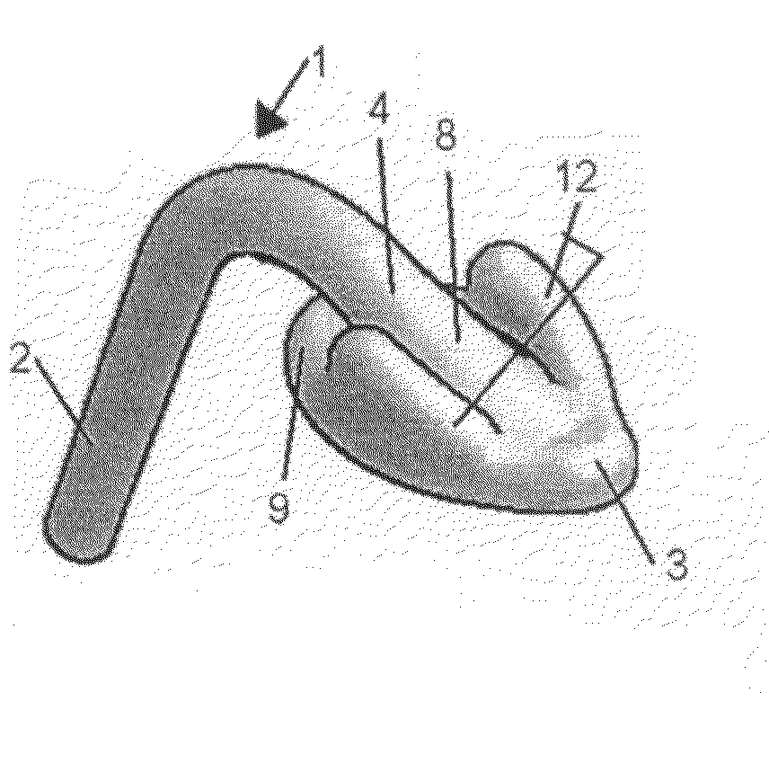
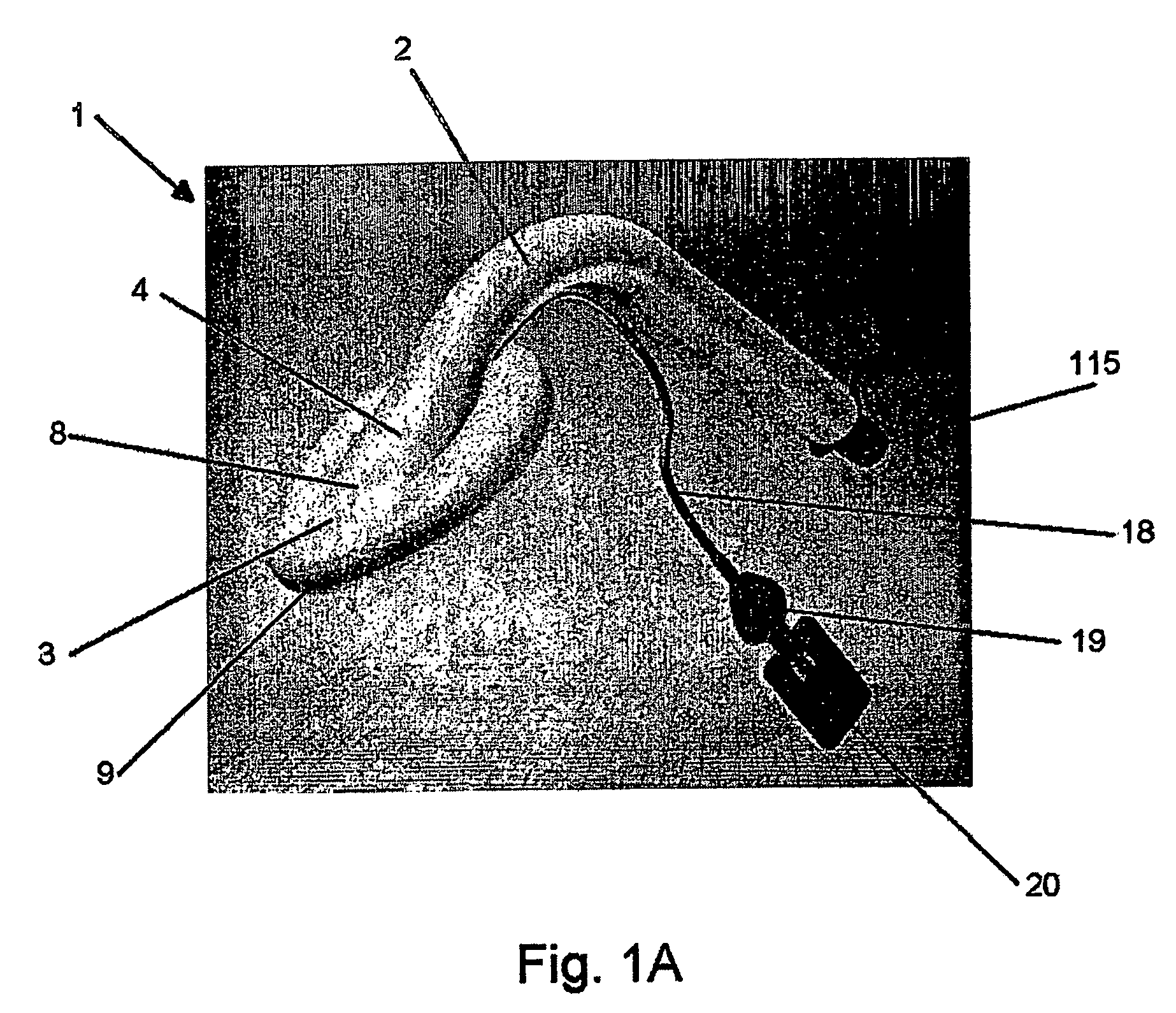
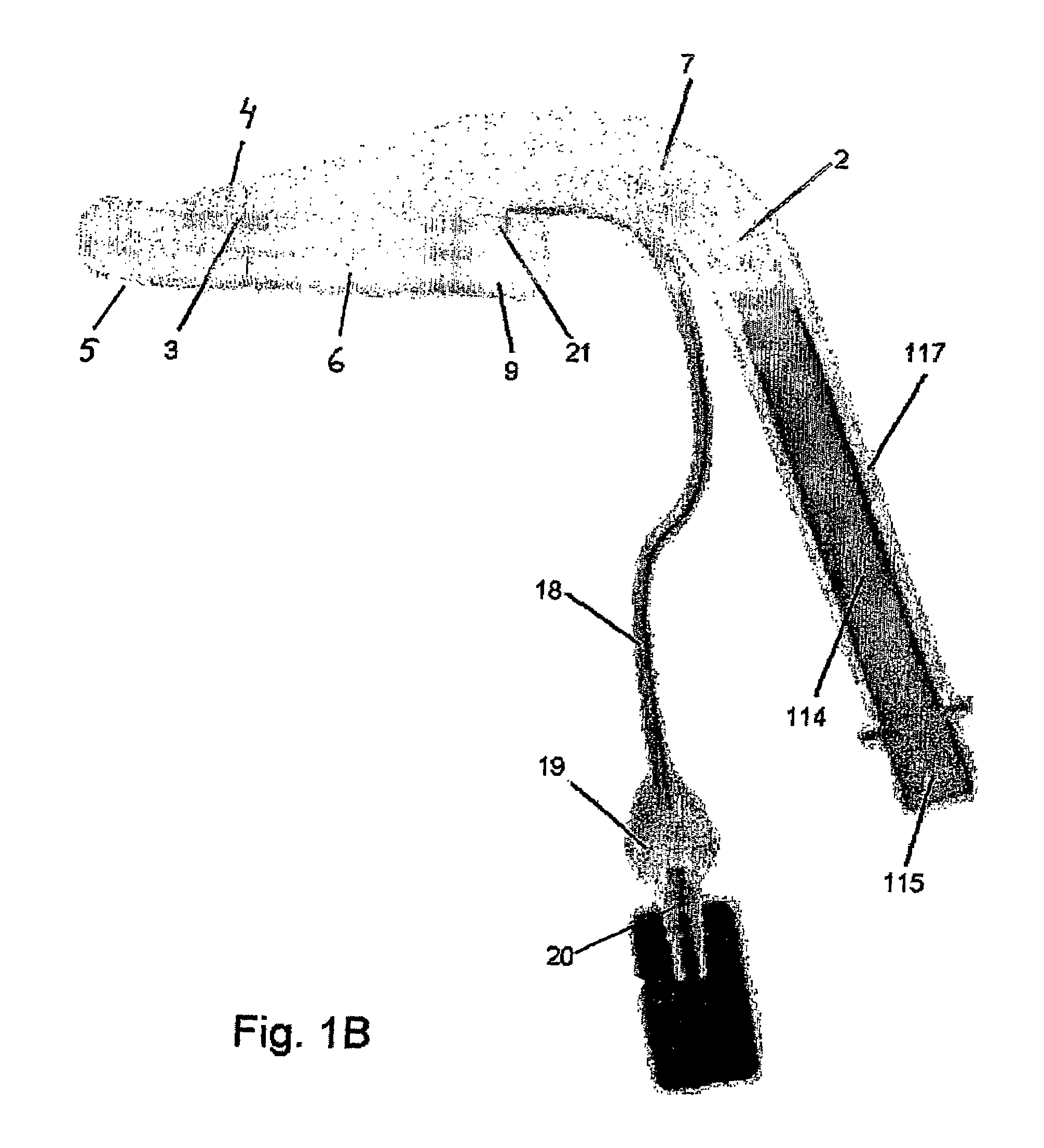
[0045]FIGS. 1A-d show an exemplary embodiment of a laryngeal mask 1 comprising at least one airway tube 2 having a circular cross section and a mask portion 3, said mask portion 3 comprising a top face 4 and a bottom face 5. The bottom face 5 comprises a lumen 6 that communicates with the tube 2 interior 7. The top face 4 comprises a closed, preferably smooth transition face 8. This face 8 is preferably convex and it may also comprise reinforcing ribs on its outer or inner face. The mask portion 3 is delimited at the periphery by an inflatable cuff 9. Its outer contours may be drop-shaped, elliptical, oval, etc. The airway tube 2 and the mask portion 3 are formed integrally within each other for providing an assembled integrated product without connecting elements between the airway tube 2 and mask portion 3.

[0046]The manufacture of the laryngeal mask takes place by an injection moulding process and the laryngeal mask is manufactured from a polymeric material. The peripheral cuff 9 ...


PUM


Abstract

The invention relates to a laryngeal mask (1) comprising at least one airway tube (2) and a mask portion (3), which mask portion (3) comprises a top face (4) and a bottom face (5), said bottom face (5) comprising a lumen (6) that communicates with the tube (2) interior (7), and said top face (4) comprising a closed transition face (8), and said mask portion (3) being at least on the bottom face in the periphery delimited by an inflatable cuff (9), and said mask portion (3) comprising a joint throughout the entire internal circumference of the cuff (9), facing towards the lumen (6) and for providing a closed cuff. Hereby a product is provided which is formed integrally with regard to mask portion and airway tube portion thereby eliminating the risk that the two parts are separated in use.

Description

BACKGROUND OF THE INVENTION[0001]1. Field of the Invention[0002]The invention relates to a laryngeal mask that includes at least one airway tube and a mask portion, the mask portion including a top face and a bottom face, the bottom face including a lumen that communicates with the tube interior, and the top face including a closed transition face; and wherein the mask portion is delimited in its periphery by an inflatable cuff at least on the bottom face. The invention also relates to a method of manufacturing such a laryngeal mask.[0003]2. The Prior Art[0004]EP-1 259 595 discloses the manufacture of laryngeal masks by means of rotational moulding, and wherein exclusively the mask portion as such is manufactured in that process.[0005]From EP-9 35 971 and EP 922 465 it is known to manufacture the mask portion by blow moulding.[0006]Laryngeal masks are used in connection with the establishment of passage of air to the respiratory tracts, while simultaneously the air passage to the oe...

Claims


Application Information

Patent Timeline
Patent Type & Authority Patents(United States)
IPC IPC(8): A61M16/00A61M16/04A61M16/08
CPCA61M16/04A61M16/0415A61M16/0409A61M16/0445
Inventor PETERSEN, LASSEHOFFMANN, PEER
Owner AMBU AS
Why Eureka
Try Eureka