Inkjet printer and a hose for use in the inkjet printer

a technology for inkjet printers and hoses, which is applied in printing and other directions, can solve the problems of insufficient air and vapor tightness of hoses, poor durability of hoses, and inability to meet the needs of use, and achieves sufficient smoothness, convenient use, and durable hoses.

Inactive Publication Date: 2010-04-13
OCE TECH
View PDF11 Cites 0 Cited by
  • Summary
  • Abstract
  • Description
  • Claims
  • Application Information

AI Technical Summary

Benefits of technology

[0004]Accordingly, It is an object of the present invention to overcome or at least mitigate this problem. To this end, the printer is provided with a hose having a wall which comprises an intermediate poly-urethane compound-containing layer provided between low density poly-ethylene compound containing layers. Surprisingly it has been found that a very durable hose can be attained, which can be advantageously used to connect the print head to the ink reservoir. Such a hose meets all the necessary requirements for an ink hose, such as water and air tightness, flexibility, and sufficient smoothness, and is easy to make due to the good processing properties of the various compounds utilized. In addition, the hose can maintain it's good properties even when the hose is used for up to a year or longer. It appears that there is no need for any extra layers besides the intermediate polyurethane compound containing layer and the LDPE compound-containing layers. Thus, in principal, a three layer wall can fulfill all the necessary requirements. However, additional layers may be provided, for example between the polyurethane compound-containing layer and one of the LDPE compound containing layers, or as an extra layer provided on the inside and / or outside of the hose, in order to meet extra or more stringent requirements. It is noted that the layers may be constituted solely out of a polyurethane material or a low density polyethylene material, respectively, or may contain other components for achieving specific desired results.
[0005]In one embodiment, the polyurethane layer comprises a thermoplastic polyurethane compound. It appears that this improves the processing properties of the urethane compound markedly, because curing processes for the polyurethane layer can be avoided in this way.
[0006]In another embodiment, the polyurethane compound-containing layer is transparent for light with a wavelength of between 400 and 750 nm. In this embodiment, the hose can be made transparent, so that the colored ink in the hose can be seen with the naked human eye. This provides the advantage that the presence, or even more importantly, the non-presence of ink can be seen when just looking at the hose. This is an important advantage in the process of trouble-shooting when the print head is malfunctioning.
[0007]In another embodiment the polyurethane compound has an elongation at break of more than 500%, as measured by the test method according to DIN 53504-S2. It appears that such a compound enables the hose to be more flexible and decreases the risk of kinks in the hose. This advantage is even more pronounced when it is combined with a polyethylene compound having an elongation at break of more than 1000%. In a further embodiment, the polyethylene compounds have a melt index of more than 5 g / 10 min, as measured by the test method according to ASTM D 1238 (190° C. / 2.16 kg). This appears to further increase the advantages of the present hose.

Problems solved by technology

However, the known inkjet printer has an important disadvantage.
The durability of the hose is relatively poor.
After a few months of operation of a typical large format printer, the air and vapor tightness of the hose can decrease to an inadequate level.
It is also known that the layers can separate which may cause mechanical damage to the hose, resulting in inadequate water vapor and air tightness.
Accordingly, the problems known before, such as the change of ink properties, degrading print quality, print head starvation etc. may again arise.
Replacement of the bad hose often requires replacement of the complete tubing system, which is relatively expensive.

Method used


Image

  • Inkjet printer and a hose for use in the inkjet printer
  • Inkjet printer and a hose for use in the inkjet printer
  • Inkjet printer and a hose for use in the inkjet printer

Examples


Embodiment Construction

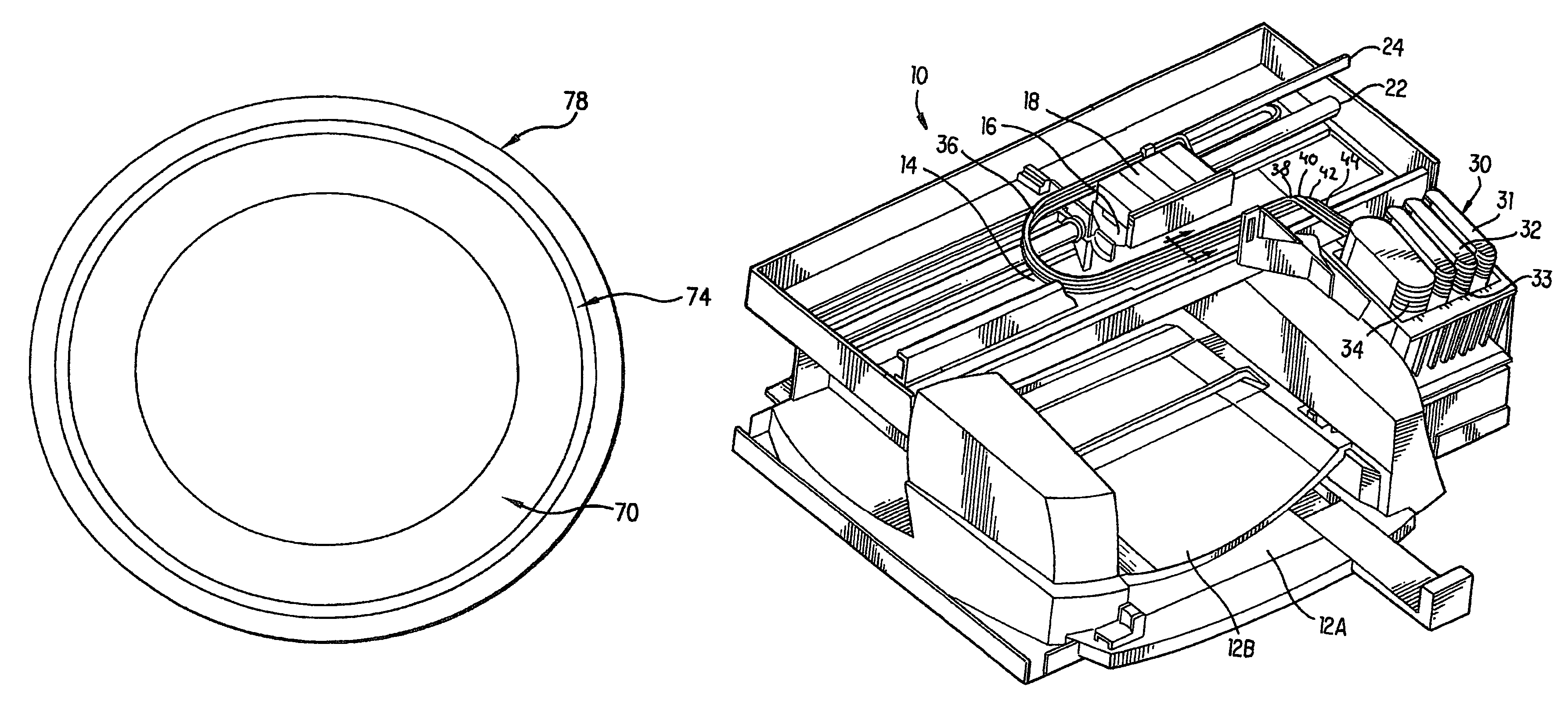
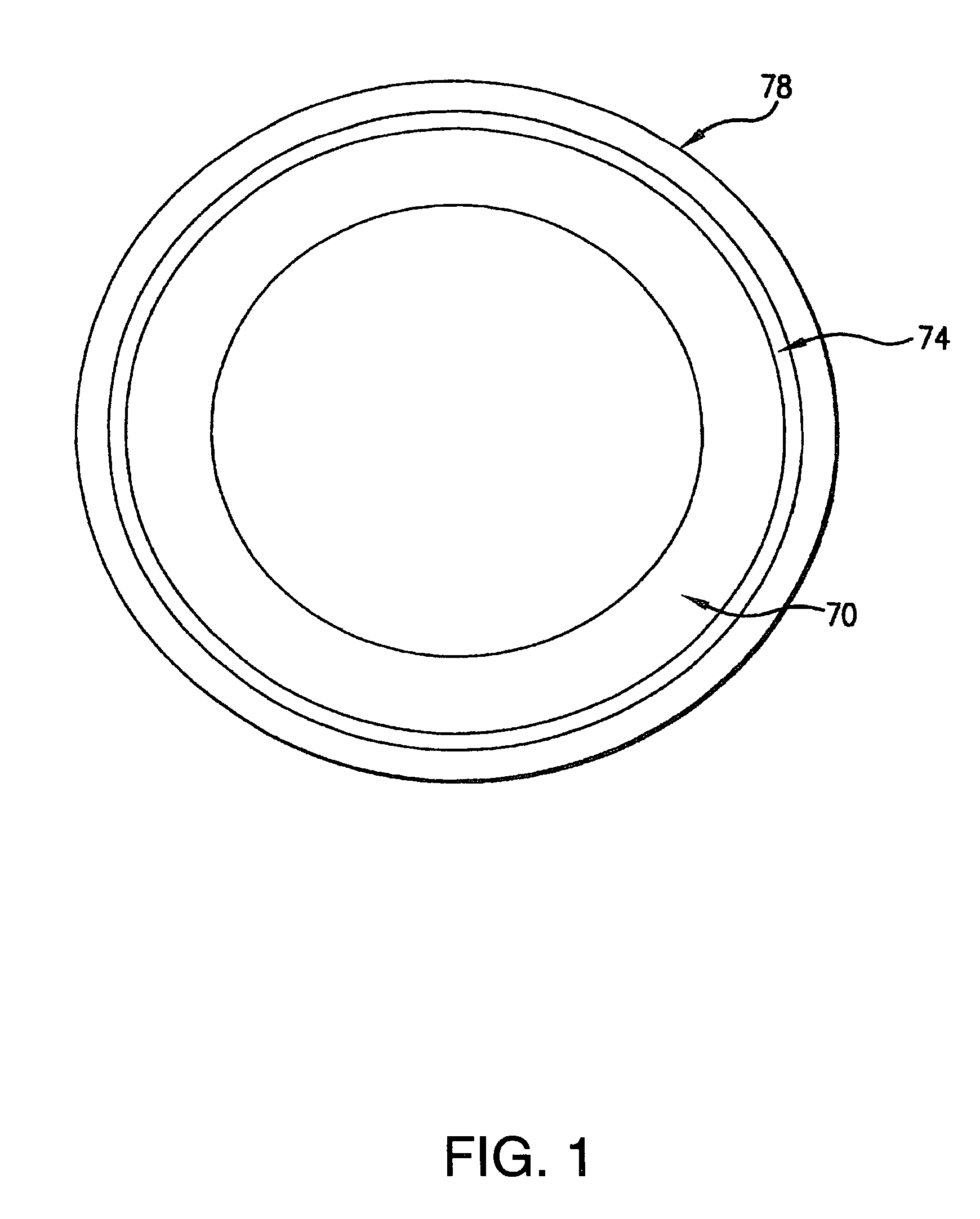
[0012]FIG. 1 schematically shows a cross-sectional view of a hose for transporting fluid ink. This hose as an internal diameter of 2.25 mm and an external diameter of 4.15 mm. Layer 70 consist essentially of LDPE (Low density polyethylene), in particular the material “Exact Plastomer 8210” available from DEX-Plastomers, a DSM / ExxonMobil Chemical joint venture registered in the Netherlands. This layer has a thickness of 0.9 mm. Layer 74 consists essentially of a 0.2 mm thick polyurethane compound, in particular the compound “Elastollan 1180 A”, a thermoplastic polyether-polyurethane, available from Elastogran GmbH (belonging to the BASF group), Lemförde, Germany. Layer 78 has a thickness of 0.8 mm and consist essentially of LDPE, in particular the material “Exact Plastomer 8210”. Such a hose can be made by well known co-extrusion processes such as for example as known from Hensen, Knappe, Potente: Kunststof-Extrusionstechnik I, München: Carl Hanser Verlag, 1989.

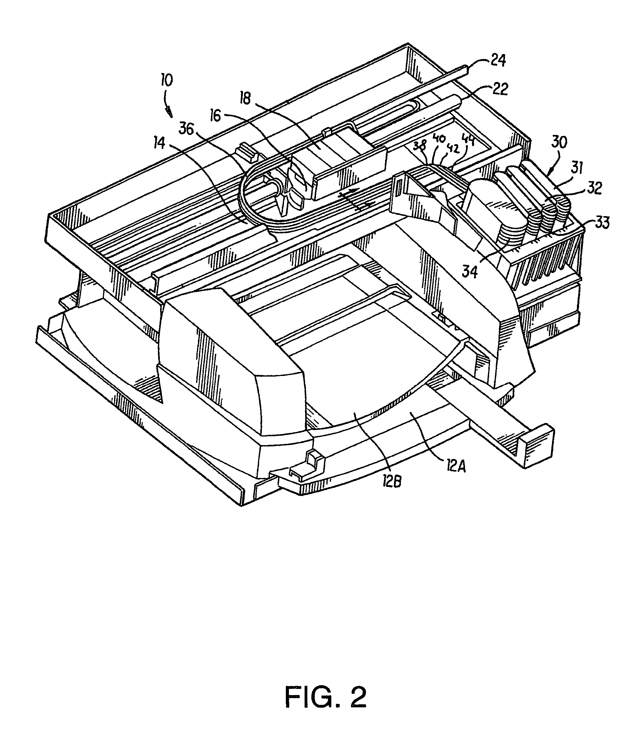
[0013]FIG. 2 is a pers...


PUM


Abstract

An inkjet printer having a print head mounted on a carriage and an off-carriage ink reservoir, the carriage being arranged for moving the print head relative to a receiving medium, wherein the printer includes a hose for connecting the print head to the reservoir to enable the supply of ink from the reservoir to the print head, the hose having a multi-layered wall, containing an intermediate poly-urethane compound containing layer disposed between low density poly-ethylene compound-containing layers.

Description

[0001]This application claims the priority benefit of European Patent Application No. 05107156.1 filed on Aug. 3, 2005, which is hereby incorporated by reference.BACKGROUND OF THE INVENTION[0002]The present invention pertains to an inkjet printer comprising a print head mounted on a carriage and an off-carriage ink reservoir, the carriage being arranged for moving the print head relative to a receiving medium. The printer comprises a hose for connecting the print head to the reservoir to enable the supply of ink from the reservoir to the print head, the hose having a multi-layered wall. The present invention also relates to the use of the hose in the inkjet printer.[0003]The printer is known from U.S. Pat. No. 5,988,801. The known printer includes a medium transporting system for transporting the receiving medium along a medium path to a print area and a scanning carriage for holding the print head. The carriage can be scanned along a scanning axis transverse to the media path at th...

Claims


Application Information

Patent Timeline
Patent Type & Authority Patents(United States)
IPC IPC(8): B41J2/175
CPCB41J2/17503B41J2/17523B41J2/17509
Inventor VAN ROY, ANTONIUS P. M. M.
Owner OCE TECH
Why Eureka
Try Eureka