Installation and method for manufacturing drip irrigation pipes

a technology of drip irrigation and manufacturing method, which is applied in the direction of manufacturing tools, food shaping, drawing profiling tools, etc., can solve the problems of deteriorating material quality, affecting and already cooling down, so as to improve the welding quality of drip irrigation pipes

Inactive Publication Date: 2010-04-13
THE MACHINES YVONAND
View PDF8 Cites 26 Cited by
  • Summary
  • Abstract
  • Description
  • Claims
  • Application Information

AI Technical Summary

Benefits of technology

[0006]It is thus an object of the present invention to improve the welding of the dripper to the pipe by realising the weld in immediate proximity to the extrusion head or directly inside the latter, i.e. in greater proximity to the melting chamber. This solution is free of the aforementioned drawbacks.
[0008]Owing to these features, it is possible to weld the drippers more reliably without having to heat the plastic material excessively, while simplifying the installation.

Problems solved by technology

At this point, the pipe has already cooled down greatly, such that the weld between the dripper and the pipe can exhibit imperfections.
Slight temperature variations can then cause deterioration in the quality of the material, which involves very strict control of the heating temperature, and consequently, an increase in the production costs.
This solution, however, involves significant extra space, complication and increased cost.

Method used


Image

  • Installation and method for manufacturing drip irrigation pipes
  • Installation and method for manufacturing drip irrigation pipes
  • Installation and method for manufacturing drip irrigation pipes

Examples


Embodiment Construction

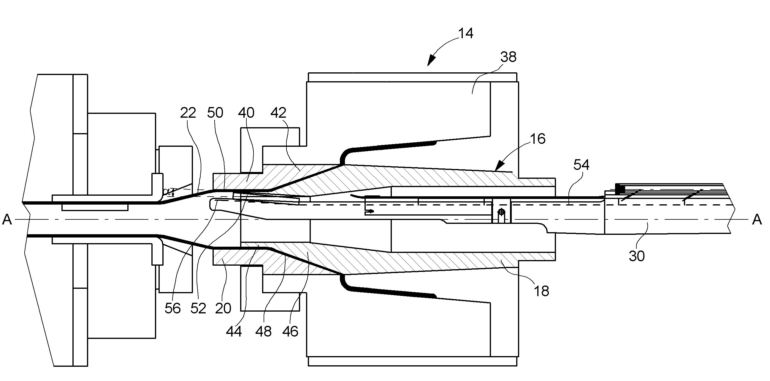
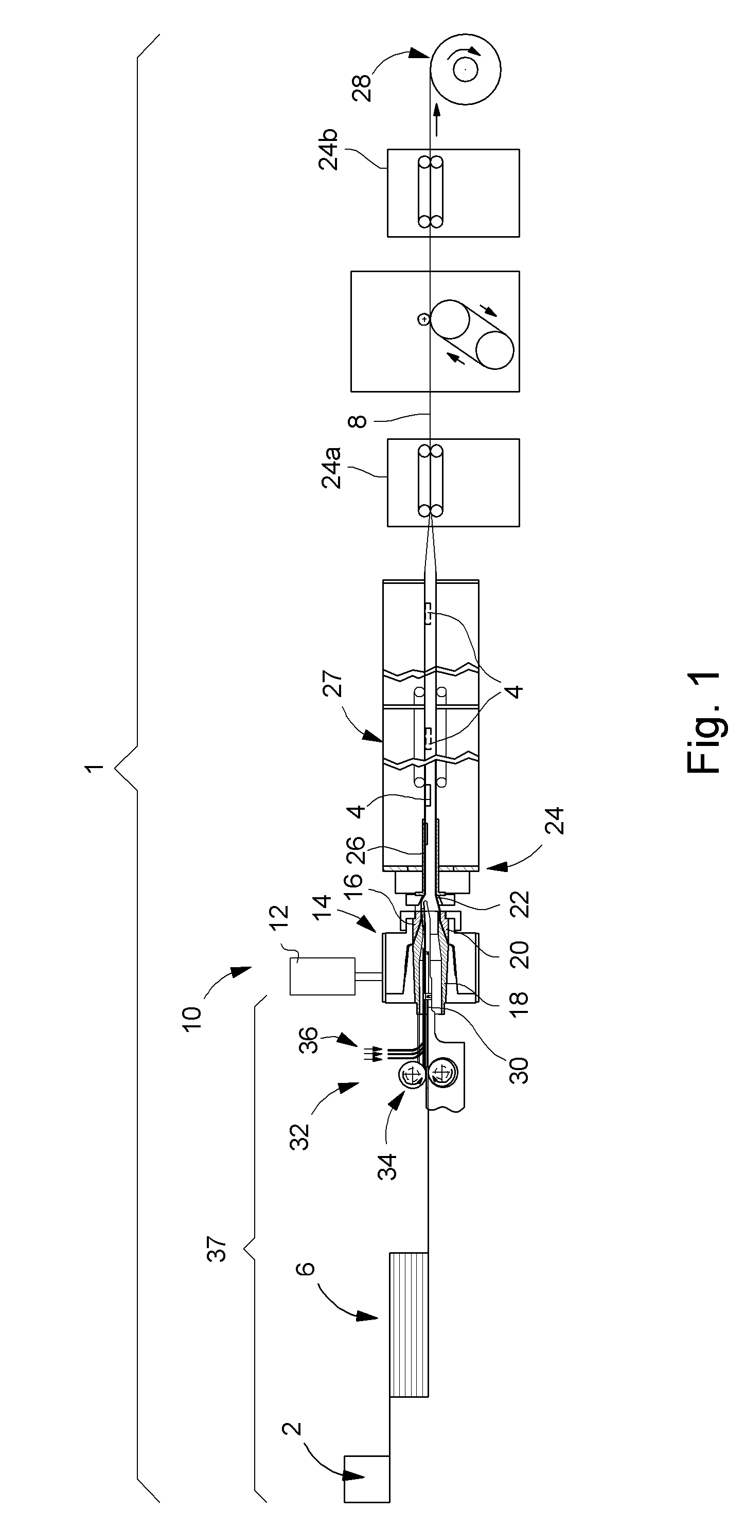
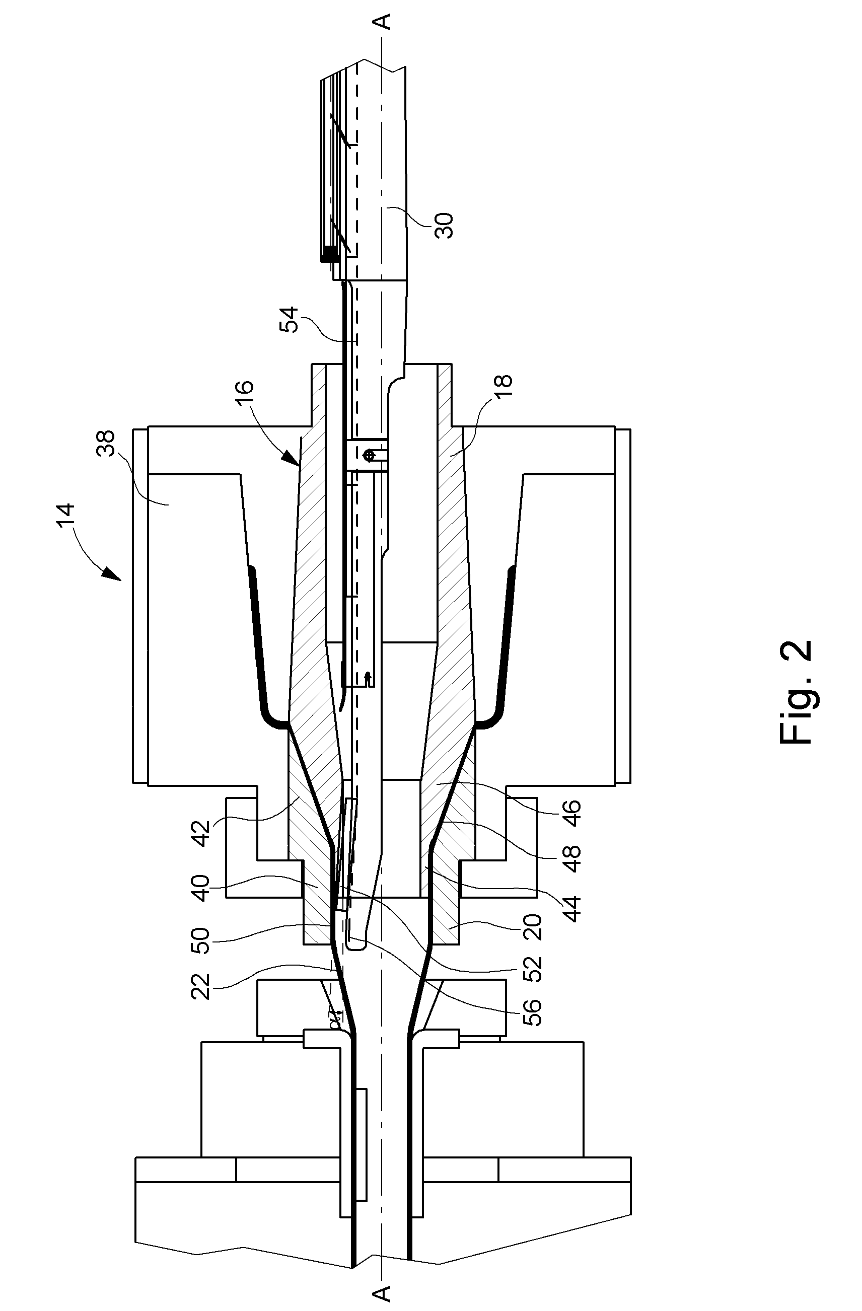
[0021]The drip type irrigation pipe manufacturing line shown in FIG. 1 and designated as a whole by the general reference numeral 1, includes in a conventional manner a magazine 2 such as a centrifugal bowl which sorts, orientates and positions drippers 4 in an accumulator device 6 according to the position that they will have to take up once they are introduced into irrigation pipe 8. After accumulator device 6 there is an extrusion station 10. This extrusion station 10 includes a melting chamber 12 for the plastic material that feeds an extrusion head 14 provided with a die 16 formed of a conical inner mandrel 18 and an outer mandrel 20 arranged such that a tubular blank 22 comes out of die 16. Blank 22 is drawn by traction stations 24a and 24b passing through calibrating means 26 and a cooling tank 27. Beyond traction station 24b, pipe 8 is wound onto a spool 28.

[0022]In order to fix drippers 4, inner mandrel 18 has an axial passage inside which there is arranged a guide support ...


PUM

PropertyMeasurementUnit
angleaaaaaaaaaa
angleaaaaaaaaaa
angleaaaaaaaaaa

Abstract

The invention concerns an installation for manufacturing a drip irrigation pipe (8) formed of a pipe (8) provided with drippers (4), including a dripper feed station (37), followed by an extrusion station (10), including an extrusion head (14) producing a tubular blank (22) and means for welding the drippers (4) to the inner wall of said blank (22), characterized in that the dripper welding means (4) include a support surface (50) and a counter-support surface (56) between which the drippers (4) are pressed against said tubular blank (22) so as to be welded thereto, said support (50) and counter-support (56) surfaces being arranged upstream of the calibrating means (24).

Description

[0001]This application claims priority from European Patent Application No. 06101518.6, filed Feb. 10, 2006, the entire disclosure of which is incorporated herein by reference.FIELD OF THE INVENTION[0002]The present invention concerns a drip irrigation pipe manufacturing line. More specifically, the invention concerns an installation of this type provided with a dripper feed device allowing improved welding of the drippers to the pipe.BACKGROUND OF THE INVENTION[0003]It is common practice to use, for certain irrigations, so-called “drip” pipes. These are pipes whose wall is pierced, at intervals fixed beforehand, with holes of small diameter through which the water flows into the ground. In order to control the flow from the holes with precision, a flow limiter, commonly called a “dripper” and formed of a hollow plastic part bonded to the inner wall of the pipe, is provided facing each hole. This part has, on the side turned towards the inner wall of the pipe, a hollow part that for...

Claims


Application Information

Patent Timeline
Patent Type & Authority Patents(United States)
IPC IPC(8): B29C49/00B05B1/30B05B15/00B29C47/00B29C65/00B31F1/00B32B37/00C08J5/00B29C48/08B29C48/09B29C48/157B29C48/92
CPCA01G25/02B29C66/836B29C65/7838B29C66/532B29C47/0064B29C66/61B29C47/028B29C47/903B29C65/028B29L2023/22B29C47/0023B29C47/1036B29C47/92B29C2947/926Y10T156/1007Y10T156/1005B29L2031/70B29C66/63B29C66/1122B29C48/92B29C48/08B29C48/09B29C48/0021B29C48/157B29C48/2883B29C48/913B29C48/919B29C48/903B29C48/908B29C2948/926Y02A40/22
Inventor KERTSCHER, EBERHARD
Owner THE MACHINES YVONAND
Why Eureka
Try Eureka