Electronic component

a technology of electronic components and components, applied in the direction of final product manufacturing, sustainable manufacturing/processing, coupling device connection, etc., can solve the problems of difficulty in reducing the size, and achieve the effect of reducing the size of the chip, and increasing the mounting strength

Inactive Publication Date: 2010-04-13
TDK CORPARATION
View PDF8 Cites 21 Cited by
  • Summary
  • Abstract
  • Description
  • Claims
  • Application Information

AI Technical Summary

Benefits of technology

[0013]It is, therefore, an object of the present invention to provide an electronic component having a large mounting strength maintaining a sufficient degree of insulation among the external electrodes despite the size of the chip is decreased.

Problems solved by technology

The coils of the winding type are accompanied by a problem of difficulty in decreasing the size due to the limitation on the structure.

Method used


Image

  • Electronic component
  • Electronic component
  • Electronic component

Examples


Embodiment Construction

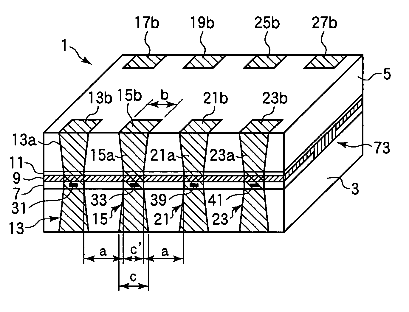
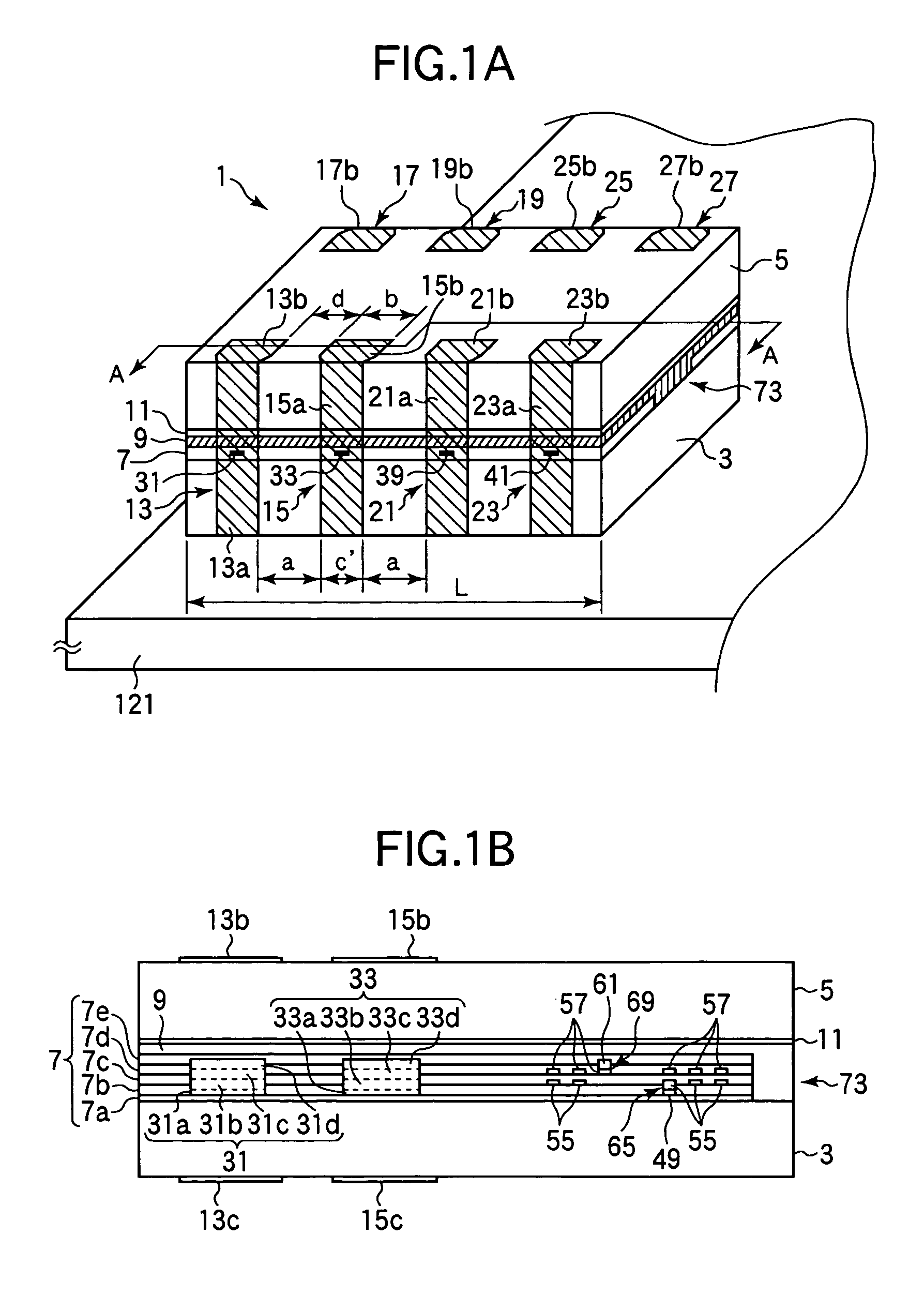
[0034]An electronic component according to an embodiment of the invention will now be described with reference to FIGS. 1A to 6. This embodiment deals, as an electronic component , with a common mode choke coil for suppressing the common mode current that becomes a cause of electromagnetic disturbance in the equilibrium transmission system. FIGS. 1A and 1B illustrate a state where a common mode choke coil array 1 integrating two common mode choke coils, is mounted on a printed circuit board (PCB) 121. FIG. 1A is a perspective view illustrating the appearance of the common mode choke coil array 1. For easy comprehension, FIG. 1A illustrates, in a perspective manner, the internal electrode terminals 31, 33, 39 and 41 which usually will not be viewed being covered with the external electrodes 13, 15, 21 and 23, and the shapes of the vicinities thereof. FIG. 1B is a sectional view cut along an imaginary line A-A in FIG. 1A.

[0035]Referring to FIG. 1A, the choke coil array 1 has a rectang...


PUM

PropertyMeasurementUnit
widthaaaaaaaaaa
shapeaaaaaaaaaa
lengthaaaaaaaaaa

Abstract

An electronic component of the surface-mounted type having a mounting surface that can be mounted on the printed circuit board, maintaining sufficient insulation among the external electrodes despite the chip size is decreased, and having a large mounting strength. In a common mode choke coil array, for example, an external electrode is constituted by electrode pads formed on the mounting surfaces of insulating substrates mounted on a PCB, and a connection electrode which electrically connects an internal electrode terminal exposed on the outer surface different from the mounting surface to the electrode pads. The connection electrodes near the internal electrode terminals have a width c′ smaller than a width b of the electrode pads as measured in the same direction.

Description

BACKGROUND OF THE INVENTION[0001]1. Field of the Invention[0002]This invention relates to a surface-mounted type electronic component having a mounting surface to be mounted on a printed circuit board or a hybrid IC (HIC).[0003]2. Description of the Related Art[0004]Coil components mounted on internal circuitry of electronic equipment such as personal computers and cell phones include those of the winding type having two copper wires wound on a ferrite core, those of the laminated type obtained by forming a coil conductor pattern on the surface of a magnetic sheet such as of ferrite and laminating the magnetic sheets, and those of the thin film type obtained by alternately forming an insulating film and a coil conductor of a thin metal film relying on a thin film-forming technology.[0005]JP-A-8-203737 discloses a common-mode choke coil that is used as a thin film type coil component. FIGS. 7A to 7C illustrate a state where a common mode choke coil array 101 formed by integrating two...

Claims


Application Information

Patent Timeline
Patent Type & Authority Patents(United States)
IPC IPC(8): H01F27/29H01F17/00H01F27/00H01F27/02H01L23/12H01R9/22H05K3/34
CPCH05K3/3442H01F17/0013H01F27/027H05K2201/09381H01R12/57H01F27/292Y02P70/50
Inventor ITO, TOMOKAZUKUDO, TAKASHIOTOMO, MAKOTO
Owner TDK CORPARATION
Why Eureka
Try Eureka