
Membrane for the protection of buildings

a membrane and building technology, applied in building components, climate change adaptation, application, etc., can solve the problems of total loss of the hollow space between the insulation and the studded membrane, collapse of the cell structure of the insulating material, etc., to achieve the same protective

Inactive Publication Date: 2010-04-20
EWALD DORKEN
View PDF16 Cites 26 Cited by
  • Summary
  • Abstract
  • Description
  • Claims
  • Application Information

AI Technical Summary

Benefits of technology

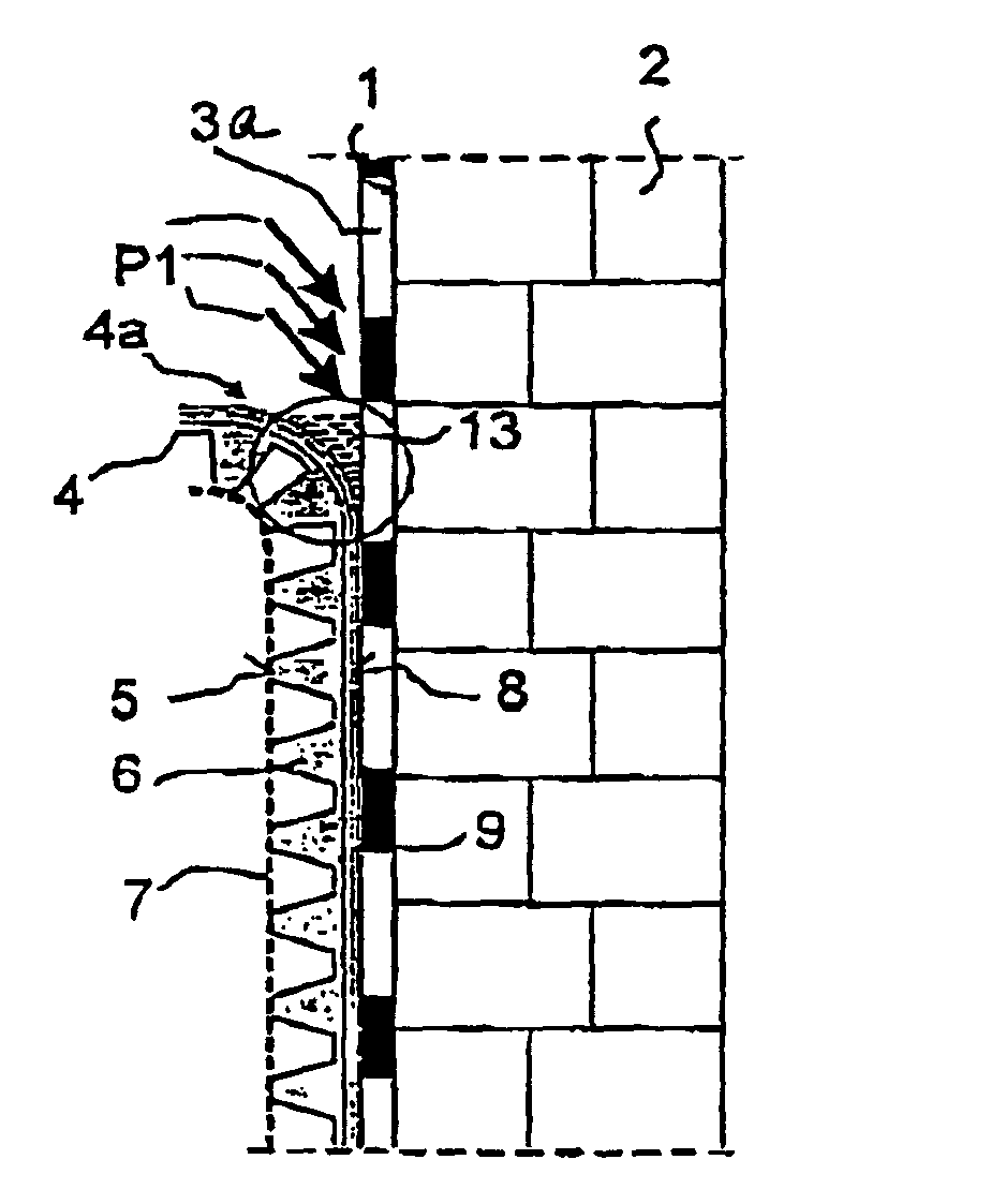
[0010]The slip surface prevents damage to an insulation of a building, which could otherwise occur when the studded membrane is taken along by the soil as the soil settles, i.e. is displaced relative to the surface of the insulation. This is because due to the pressure of the soil, the reverse side of the studded membrane lies against the surface of the insulation under a correspondingly high pressure. The insulation may be of foamed plastic, in particular in the form of boards as a so-called perimeter insulation, which are fastened to the surface of the exterior wall of the foundations of a building, as initially pointed out. The present approach can, however, also be applied to water-impermeable concrete or to a seal of a bitumous sheet (e.g. cold sealing bitumous sheeting).
[0041]In any case, an improved studded membrane and / or seal according to the present invention, with or without slip film, has the same protective effect as the commercially available protective membrane, such as DELTA-GEO DRAIN®, but avoids the possible collection of water between the studded membrane and the insulation on the wall to be protected, or the creation of water pockets between the thick layer and the slip film in the case of a top edge seam which is not sealed.

Problems solved by technology

If high soil pressures are to be absorbed by the studded membrane and transferred to the insulation of the wall, this may lead to a collapse of the cell structure of the insulating material, if the soil pressure is only transferred via the small surface percentage taken up by the end-faces of the studs.
This results in an indentation of the studs into the insulating material so that the studded membrane loses its ventilating function.
Since the soil pressure gets higher as the depth increases, a total loss of the hollow space between the insulation and the studded membrane may result, in particular at the foot of the wall.
Moreover, there is a risk that the raised, reverse-side studs of the studded membrane prevent the studded membrane from sliding on the insulation board or the surface of the insulation without considerable frictional resistance when the soil settles.
When dampness penetrates into the space between the reverse side of the studded membrane and the wall to be protected, there is a risk with conventional studded membranes, irrespective of whether the studded membrane has been formed with unilaterally or bilaterally formed studs, that water will accumulate between the studded membrane and the wall.

Method used


Image

  • Membrane for the protection of buildings
  • Membrane for the protection of buildings
  • Membrane for the protection of buildings

Examples


Embodiment Construction

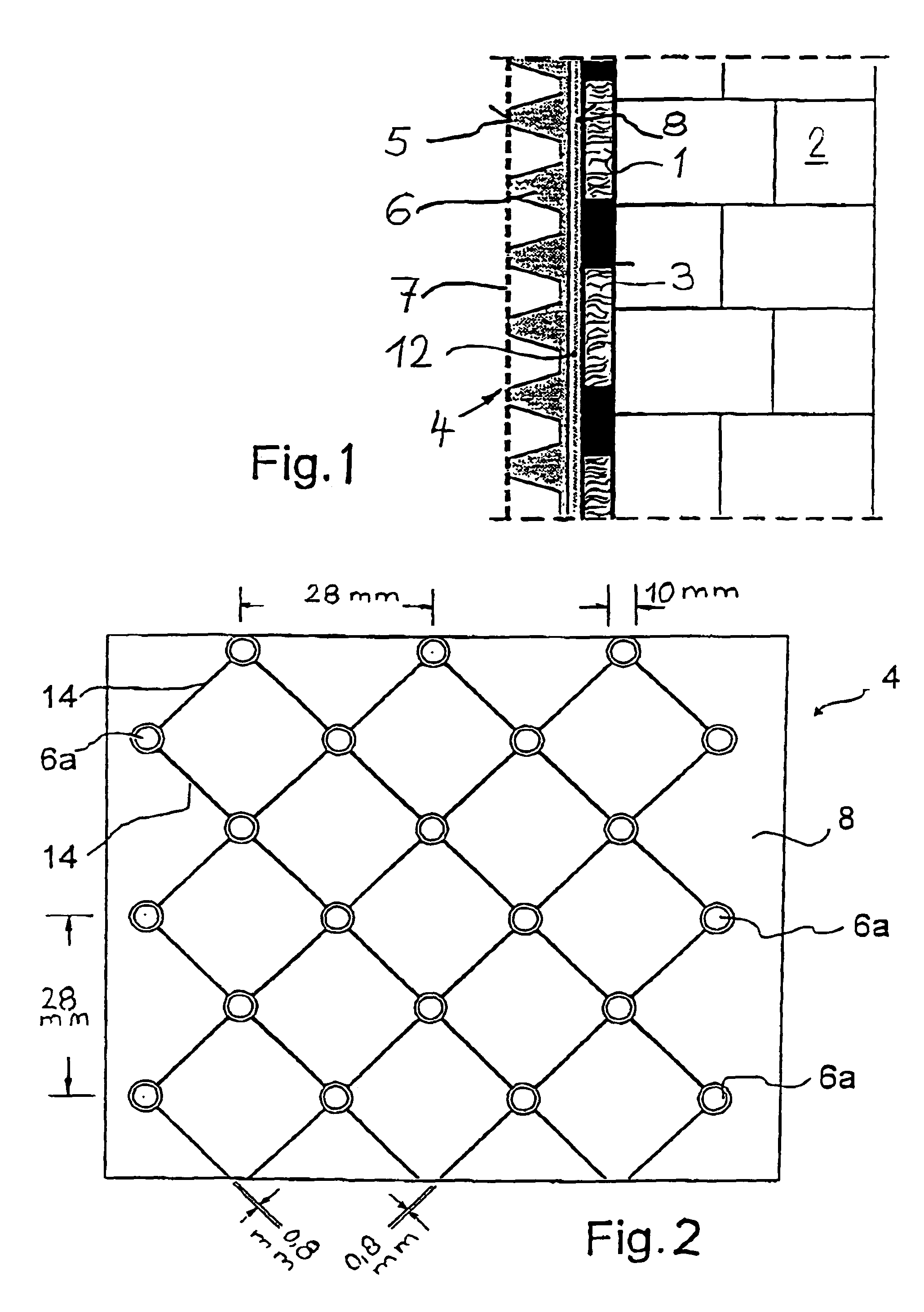
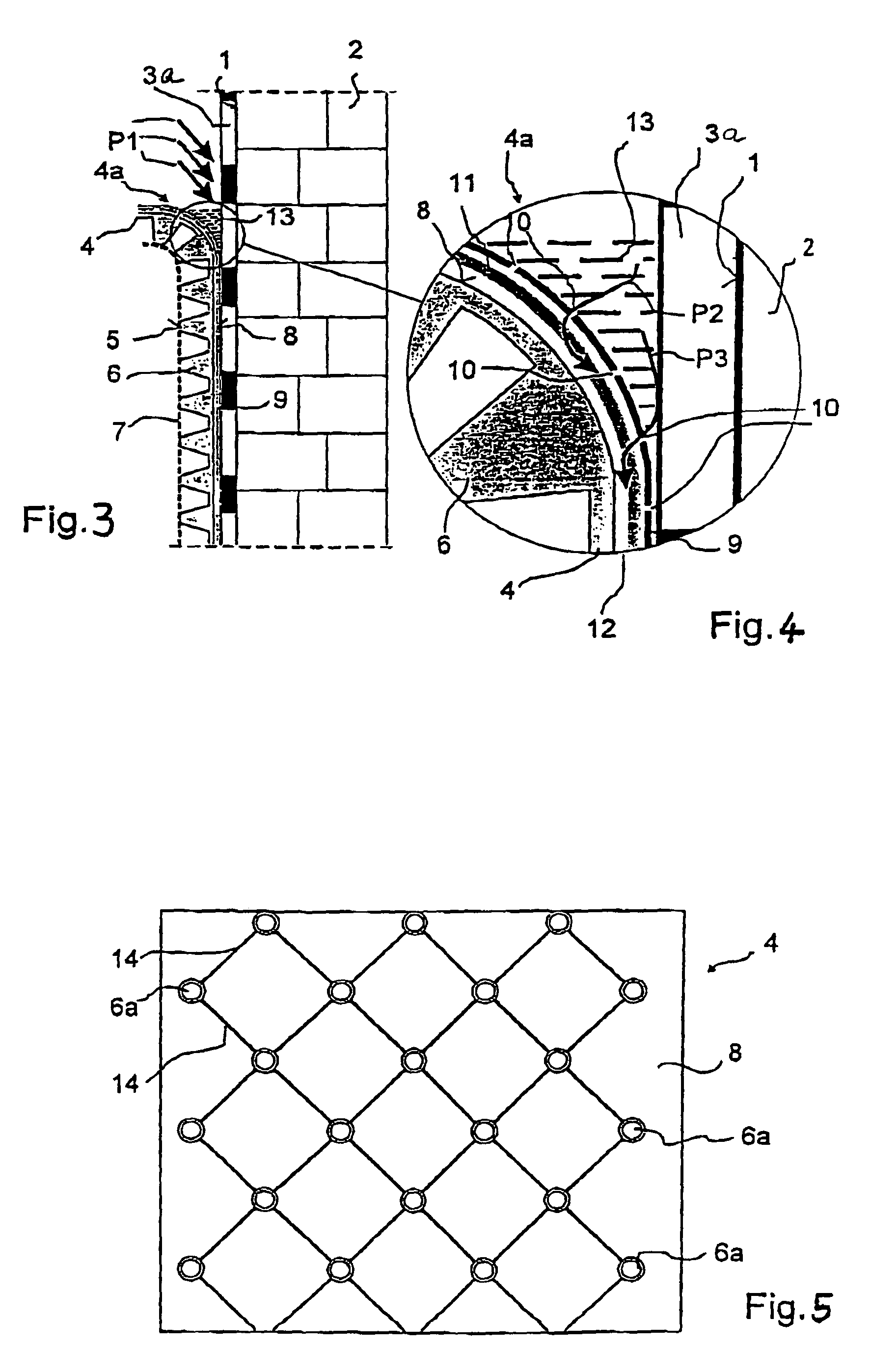
[0051]In the cross-sectional view shown in FIG. 1, an insulation 3, e.g. a perimeter insulation of foamed plastic, is mounted on an outer surface 1 of a building 2. To protect insulation 3 against damage caused by the soil (not shown), a studded membrane 4 of plastic (e.g. PE) is mounted in front of insulation 3, fixed either to the latter or to the outer surface 1 of building 2.

[0052]A water-permeable fleece 7 is mounted on the end faces 5 of studs 6 of studded membrane 4 for draining the adjacent soil. Water penetrating through fleece 7 into the space between fleece 7 and studded membrane 4 is drained towards the bottom by channels formed between studs 6.

[0053]To form a drainage 12 on the reverse side 8 of studded membrane 4, channels 14 running diagonally—relative to the longitudinal direction of studded membrane 4—are provided between stud funnels 6a (cf. FIG. 2). Channels 14, which are about 0.8 mm wide and about 0.5 mm deep, are sufficient. The diagonal interval of channels 14...


PUM


Abstract

A studded membrane is proposed for the protection of buildings with a drainage and slip surface formed on the reverse side thereof. This ensures that water is drainedbetween the studded membrane and the exterior surface of the building,between the studded membrane and the seal,between the studded membrane and the insulation.

Description

BACKGROUND OF THE INVENTION[0001]The present invention relates to a studded or dimpled membrane for the protection of buildings, and to a seal manufactured using the studded membrane.[0002]The present invention refers to a studded membrane having studs on the front surface suitable to support a filter fleece. The studded membrane is usually manufactured in a flexible way from a plastic sheet on an embossing roller used to shape the studs in a continuous process, cut to the desired length and rolled up for storage and transport. To protect the walls of buildings, in particular at the underground level, the studded membrane is attached to the wall to be protected.[0003]From DE 31 27 265, a studded membrane is known having studs with planar end faces formed on either side of a central plane. The reverse side studs provide a deeply indented surface and serve to ventilate an air-gap and space respectively between the surface of the wall to be protected and the studded membrane. The stud ...

Claims


Application Information

Patent Timeline
Patent Type & Authority Patents(United States)
IPC IPC(8): E02D19/00E04H9/14
CPCE04H9/145Y02A50/00
Inventor SCHROER, JORNRAIDT, HEINZ PETERKLINGELHAGE, NORBERT
Owner EWALD DORKEN
Learn More