
Injector

a technology of injector and needle, which is applied in the direction of fuel injection apparatus, charge feed system, engine components, etc., can solve the problems of unstable injection quantity, achieve high accuracy, reduce the effect of injection quantity

Inactive Publication Date: 2010-04-20
DENSO CORP
View PDF15 Cites 8 Cited by
  • Summary
  • Abstract
  • Description
  • Claims
  • Application Information

AI Technical Summary

Benefits of technology

The present invention provides an injector with a stopper mechanism for limiting the valve opening lift position of the needle, which ensures stable injection quantity regardless of the displacement variation of the piezoelectric actuator. The injector has a valve body with a movable sleeve, a cylindrical movable sleeve, a valve head section, a needle, a pressure control chamber, and a lift limiting member. The lift limiting member is a single plate member with a hole section and a stopper face that contacts the axial end face of the needle when the needle lifts by a predetermined amount. The needle head section is formed in the shape of a cylinder, and the fluid passage through which high pressure fluid flows is formed in the cylindrical shape. The plate member is formed with a plurality of transmitting sections at equal intervals along a circumferential direction. The needle head section is formed in the shape of a ring, and the stopper face is formed in a ring shape. The injector has a spring that biases the needle in a valve closing direction, and the valve body has a cylindrical wall section for holding the outer periphery of the movable sleeve. The plate member is formed with a single plate member with the same thickness from the stopper face to the certain face. These features enable the injector to achieve stable injection quantity and prevent increase in size.

Problems solved by technology

Accordingly, there has been a problem that the injection quantity is not stabilized due to the displacement variation of the piezoelectric actuator 100.

Method used


Image

  • Injector
  • Injector
  • Injector

Examples


first embodiment

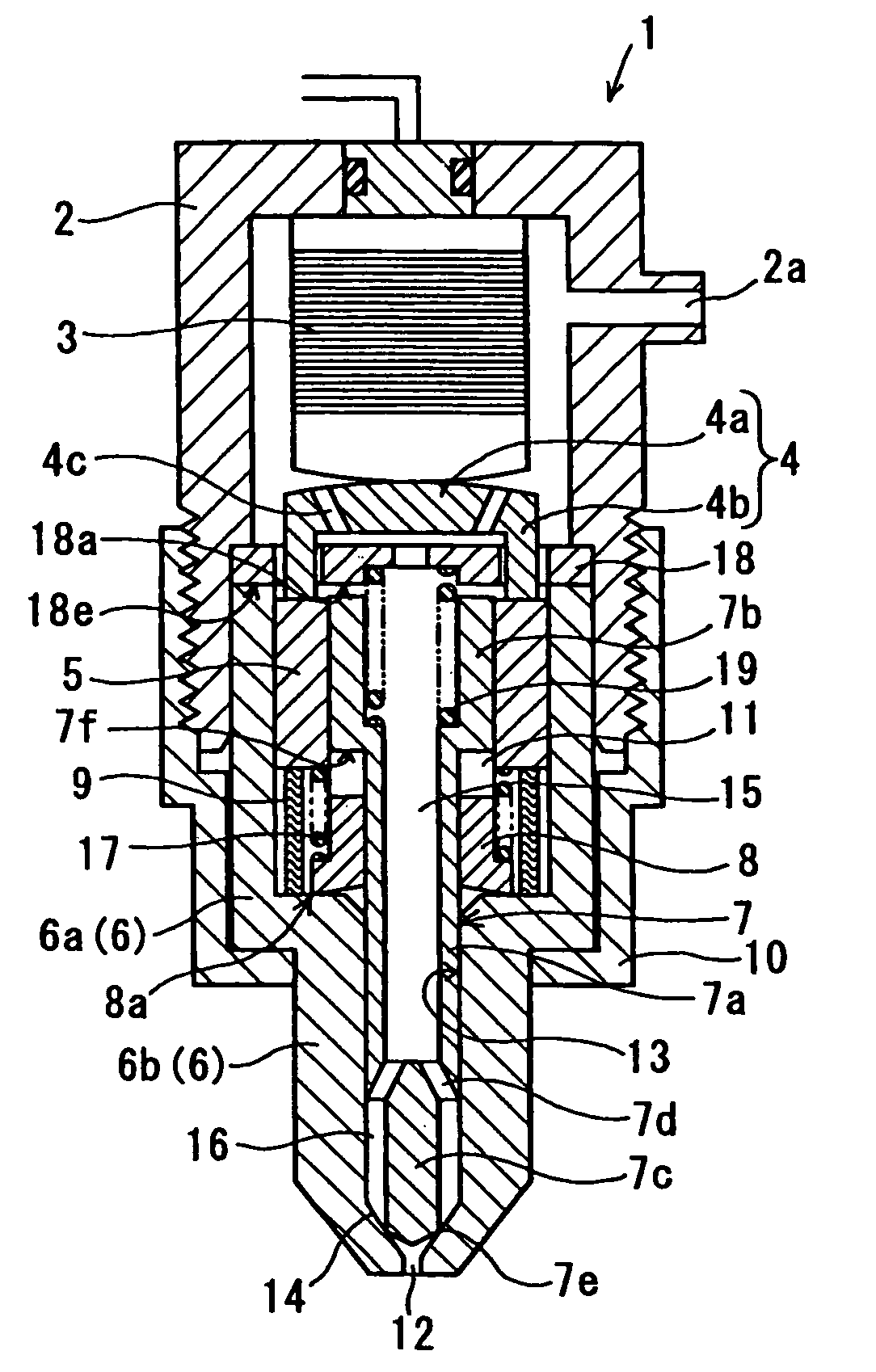
[0029]Referring to FIG. 1, an injector 1 according to the present invention is illustrated. The injector 1 of the present embodiment is a device that is attached to each cylinder of a diesel engine and that injects high pressure fuel, which is supplied from a common rail (not shown), directly into a combustion chamber in the cylinder, for example.

[0030]As shown in FIG. 1, the injector 1 includes a valve housing 2, a piezoelectric actuator 3, a pressurizing piston 4, a movable sleeve 5, a valve body 6, a needle 7, an inner sleeve 8, a lift limiting member and the like.

[0031]The valve housing 2 defines a sealed internal space between the valve housing 2 and the valve body 6 and is formed with a fuel inlet 2a connected to the common rail through a fuel pipe (not shown). The internal space is filled with the high pressure fuel flowing in from the fuel inlet 2a.

[0032]The piezoelectric actuator 3 is a common actuator having a capacitor structure of alternately laminated piezoelectric cer...

second embodiment

[0061]Next, an injector 1 according to the present invention will be described. FIG. 4 is a sectional view showing the injector 1 according to the present embodiment. The injector 1 of the present embodiment is an example locating a sealing member 20 such as an O-ring in a fitting section between the valve housing 2 and the valve body 6 as shown in FIG. 4.

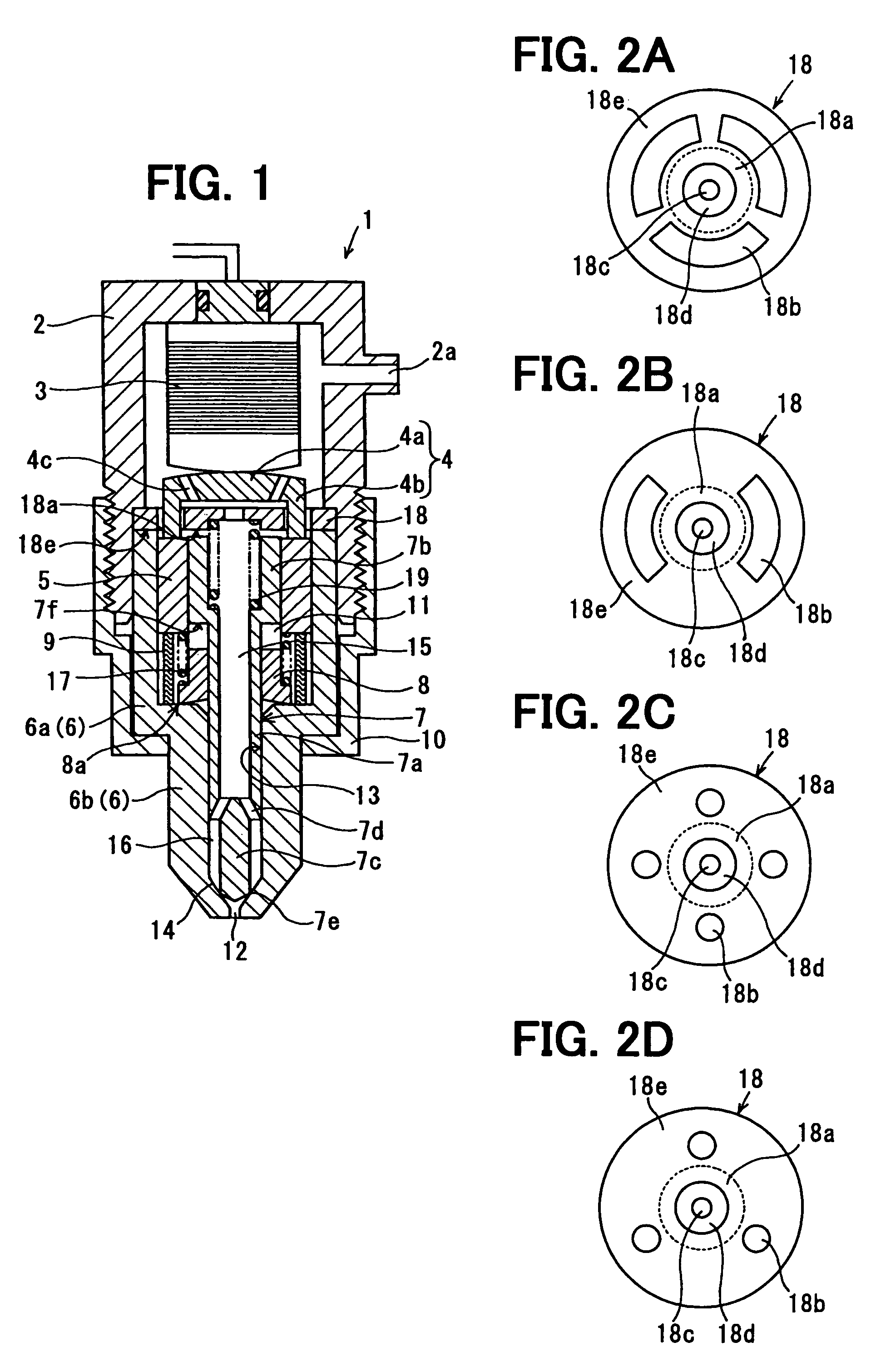
[0062]In the structure of the first embodiment, the peripheral edge portion of the plate member 18 is held between the step of the valve housing 2 and the axial end face of the cylindrical wall section 6a of the valve body 6. Thus, the fuel sealing is made by achieving close contact between the both metal surfaces. Therefore, the sealing performance has to be maintained by the tightening force (axial force) of the retaining nut 10.

[0063]As contrasted thereto, in the structure of the present embodiment, the fuel sealing is achieved by the sealing member 20. Accordingly, as compared with the structure of the first embodiment, the tig...


PUM


Abstract

An injector has a lift limiting member provided by a single plate member. The plate member has a stopper face, multiple hole sections, a flow passage hole, and a spring seat face. An axial end face of a needle head section of a needle contacts the stopper face when the needle lifts by a predetermined amount. Transmitting sections of a pressurizing piston are loosely inserted in the hole sections. High pressure fuel can pass through the flow passage hole. The spring seat face receives an end portion of a spring that biases the needle in a valve closing direction. The lift limiting member limits a valve opening lift position of the needle, so a stable injection quantity is obtained. Thus, a surface area of the single plate member can be used in multiple functions.

Description

CROSS REFERENCE TO RELATED APPLICATION[0001]This application is based on and incorporates herein by reference Japanese Patent Application No. 2007-54070 filed on Mar. 5, 2007.BACKGROUND OF THE INVENTION[0002]1. Field of the Invention[0003]The present invention relates to an injector that controls opening / closing action of a needle by increasing / decreasing control pressure of a pressure control chamber through movement of a pressurizing piston driven by a piezoelectric actuator.[0004]2. Description of Related Art[0005]An injector using an electromagnetic valve as an actuator is commonly used. In order to realize a large flow rate and high response, an injector using a piezoelectric actuator with a large generative force and high response is proposed.[0006]For example, an injector described in Patent document 1 (International Publication No. 2005 / 075811) has a piezoelectric actuator 100 that makes a displacement when voltage is applied thereto, a pressurizing piston 110 driven by the ...

Claims


Application Information

Patent Timeline
Patent Type & Authority Patents(United States)
IPC IPC(8): B05B1/08
CPCF02M51/0603F02M61/20F02M2200/306
Inventor MOCHIZUKI, KOUICHIKUROYANAGI, MASATOSHI
Owner DENSO CORP
Learn More